AIM
4/3/14
2−3−7
Airport Marking Aids and Signs
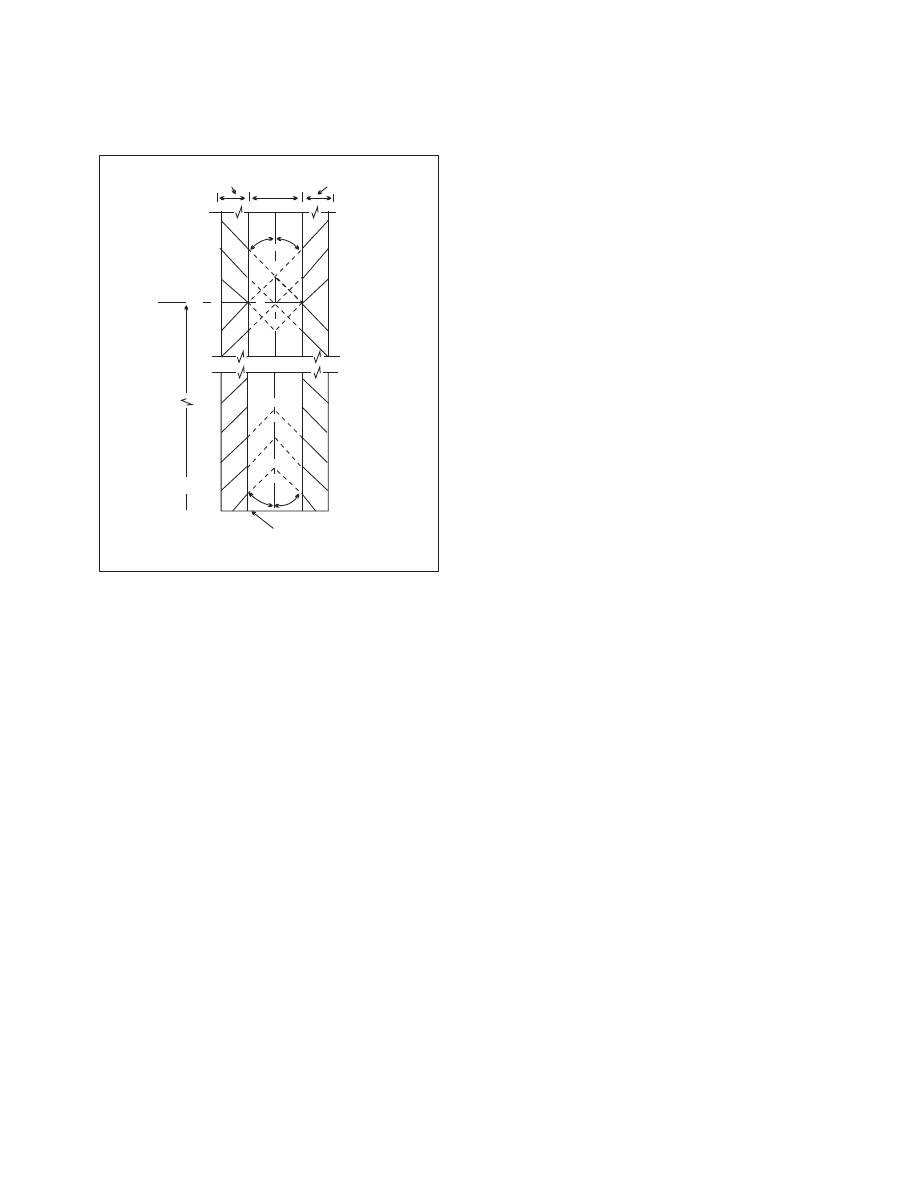
FIG 2
−3−5
Runway Shoulder Markings
RUNWAY THRESHOLD
MIDPOINT OF
RUNWAY
SHOULDER
SHOULDER
RUNWAY
45°
45°
45°
45°
2
−
3
−
4. Taxiway Markings
a. General.
All taxiways should have centerline
markings and runway holding position markings
whenever they intersect a runway. Taxiway edge
markings are present whenever there is a need to
separate the taxiway from a pavement that is not
intended for aircraft use or to delineate the edge of the
taxiway. Taxiways may also have shoulder markings
and holding position markings for Instrument
Landing System/Microwave Landing System (ILS/
MLS) critical areas, and taxiway/taxiway
intersection markings.
REFERENCE
−
AIM, Holding Position Markings, Paragraph 2
b. Taxiway Centerline.
1. Normal Centerline.
The taxiway centerline
is a single continuous yellow line, 6 inches (15 cm) to
12 inches (30 cm) in width. This provides a visual cue
to permit taxiing along a designated path. Ideally, the
aircraft should be kept centered over this line during
taxi. However, being centered on the taxiway
centerline does not guarantee wingtip clearance with
other aircraft or other objects.
2. Enhanced Centerline.
At some airports,
mostly the larger commercial service airports, an
enhanced taxiway centerline will be used. The
enhanced taxiway centerline marking consists of a
parallel line of yellow dashes on either side of the
normal taxiway centerline. The taxiway centerlines
are enhanced for a maximum of 150 feet prior to a
runway holding position marking. The purpose of
this enhancement is to warn the pilot that he/she is
approaching a runway holding position marking and
should prepare to stop unless he/she has been cleared
onto or across the runway by ATC. (See FIG 2−3−8.)
c. Taxiway Edge Markings.
Taxiway edge
markings are used to define the edge of the taxiway.
They are primarily used when the taxiway edge does
not correspond with the edge of the pavement. There
are two types of markings depending upon whether
the aircraft is supposed to cross the taxiway edge:
1. Continuous Markings.
These consist of a
continuous double yellow line, with each line being
at least 6 inches (15 cm) in width spaced 6 inches
(15 cm) apart. They are used to define the taxiway
edge from the shoulder or some other abutting paved
surface not intended for use by aircraft.
2. Dashed Markings.
These markings are
used when there is an operational need to define the
edge of a taxiway or taxilane on a paved surface
where the adjoining pavement to the taxiway edge is
intended for use by aircraft, e.g., an apron. Dashed
taxiway edge markings consist of a broken double
yellow line, with each line being at least 6 inches
(15 cm) in width, spaced 6 inches (15 cm) apart (edge
to edge). These lines are 15 feet (4.5 m) in length with
25 foot (7.5 m) gaps. (See FIG 2−3−9.)
d. Taxi Shoulder Markings.
Taxiways, holding
bays, and aprons are sometimes provided with paved
shoulders to prevent blast and water erosion.
Although shoulders may have the appearance of full
strength pavement they are not intended for use by
aircraft, and may be unable to support an aircraft.
Usually the taxiway edge marking will define this
area. Where conditions exist such as islands or
taxiway curves that may cause confusion as to which
side of the edge stripe is for use by aircraft, taxiway
shoulder markings may be used to indicate the
pavement is unusable. Taxiway shoulder markings
are yellow. (See FIG 2−3−10.)