AIM
8/15/19
5
−
4
−
14
Arrival Procedures
7.
TAAs may be modified from the standard size
and shape to accommodate operational or ATC
requirements. Some areas may be eliminated, while
the other areas are expanded. The “T” design may be
modified by the procedure designers where required
by terrain or ATC considerations. For instance, the
“T” design may appear more like a regularly or
irregularly shaped “Y,” upside down “L,” or an “I.”
(a)
FIG 5
−
4
−
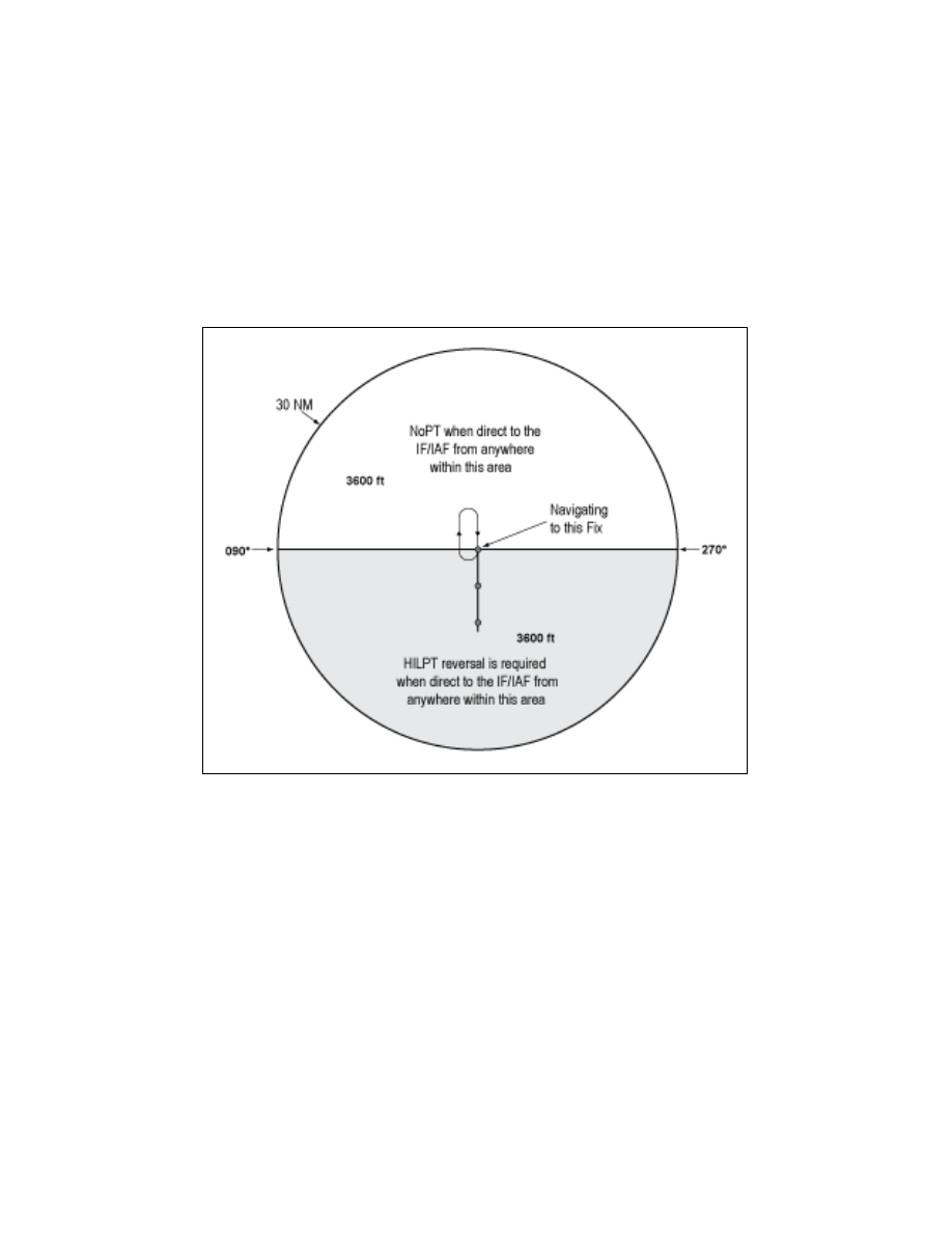
7 depicts a TAA without a left
base leg and right base leg. In this generalized
example, pilots approaching on a bearing TO the
IF/IAF from 271 clockwise to 089 are expected to
execute a course reversal because the amount of turn
required at the IF/IAF exceeds 90 degrees. The term
“NoPT” will be annotated on the boundary of the
TAA icon for the other portion of the TAA.
FIG 5
−
4
−
7
TAA with Left and Right Base Areas Eliminated
(b)
FIG 5
−
4
−
8 depicts another TAA modific-
ation that pilots may encounter. In this generalized
example, the left base area and part of the straight-in
area have been eliminated. Pilots operating within the
TAA between 210 clockwise to 360 bearing TO the
IF/IAF are expected to proceed direct to the IF/IAF
and then execute the course reversal in order to
properly align the aircraft for entry onto the
intermediate segment or to avoid an excessive
descent rate. Aircraft operating in areas from 001
clockwise to 090 bearing TO the IF/IAF are expected
to proceed direct to the right base IAF and not execute
course reversal maneuver. Aircraft cleared direct the
IF/IAF by ATC in this sector will be expected to
accomplish HILTP. Aircraft operating in areas 091
clockwise to 209 bearing TO the IF/IAF are expected
to proceed direct to the IF/IAF and not execute the
course reversal. These two areas are annotated
“NoPT” at the TAA boundary of the icon in these
areas when displayed on the approach chart’s plan
view.