AIM
8/15/19
1
−
1
−
8
Navigation Aids
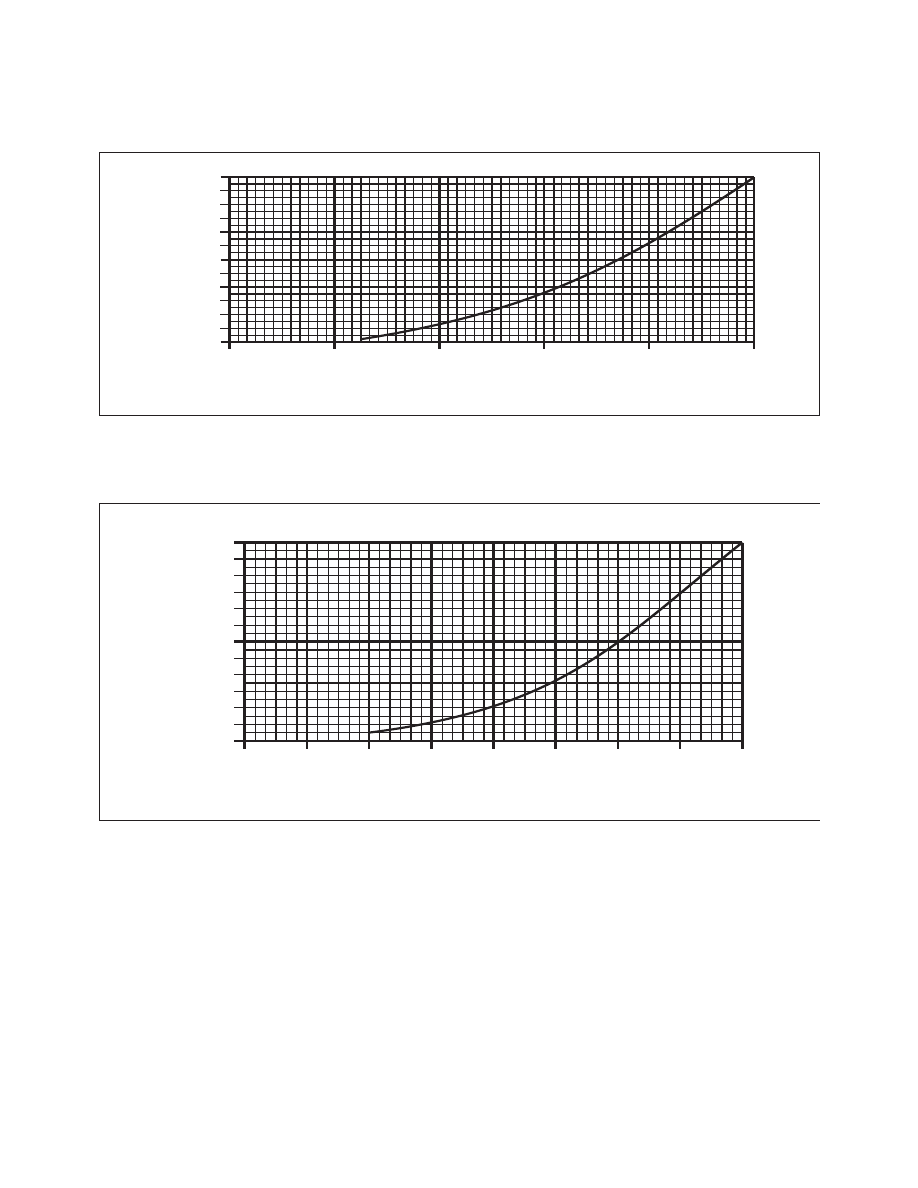
FIG 1
−
1
−
4
Service Volume Lower Edge Terminal
1000
500
0
0
5
10
15
20
25
DISTANCE TO THE STATION IN NM
ALTITUDE IN FEET
FIG 1
−
1
−
5
Service Volume Lower Edge
Standard High and Low
1000
500
0
0
10
20
30
40
DISTANCE TO THE STATION IN NM
ALTITUDE IN FEET
5
15
25
35
1
−
1
−
9. Instrument Landing System (ILS)
a. General
1.
The ILS is designed to provide an approach
path for exact alignment and descent of an aircraft on
final approach to a runway.
2.
The ground equipment consists of two highly
directional transmitting systems and, along the
approach, three (or fewer) marker beacons. The
directional transmitters are known as the localizer
and glide slope transmitters.
3.
The system may be divided functionally into
three parts:
(a) Guidance information:
localizer, glide
slope;
(b) Range information:
marker beacon,
DME; and
(c) Visual information:
approach lights,
touchdown and centerline lights, runway lights.
4.
Precision radar, or compass locators located
at the Outer Marker (OM) or Middle Marker (MM),
may be substituted for marker beacons. DME, when