AIM
8/15/19
1
−
1
−
9
Navigation Aids
specified in the procedure, may be substituted for the
OM.
5.
Where a complete ILS system is installed on
each end of a runway; (i.e., the approach end of
Runway 4 and the approach end of Runway 22) the
ILS systems are not in service simultaneously.
b. Localizer
1.
The localizer transmitter operates on one of
40 ILS channels within the frequency range of
108.10 to 111.95 MHz. Signals provide the pilot with
course guidance to the runway centerline.
2.
The approach course of the localizer is called
the front course and is used with other functional
parts, e.g., glide slope, marker beacons, etc. The
localizer signal is transmitted at the far end of the
runway. It is adjusted for a course width of (full scale
fly
−
left to a full scale fly
−
right) of 700 feet at the
runway threshold.
3.
The course line along the extended centerline
of a runway, in the opposite direction to the front
course is called the back course.
CAUTION
−
Unless the aircraft’s ILS equipment includes reverse
sensing capability, when flying inbound on the back
course it is necessary to steer the aircraft in the direction
opposite the needle deflection when making corrections
from off
−
course to on
−
course. This “flying away from the
needle” is also required when flying outbound on the
front course of the localizer. Do not use back course
signals for approach unless a back course approach
procedure is published for that particular runway and the
approach is authorized by ATC.
4.
Identification is in International Morse Code
and consists of a three
−
letter identifier preceded by
the letter I (
D D
) transmitted on the localizer
frequency.
EXAMPLE
−
I
−
DIA
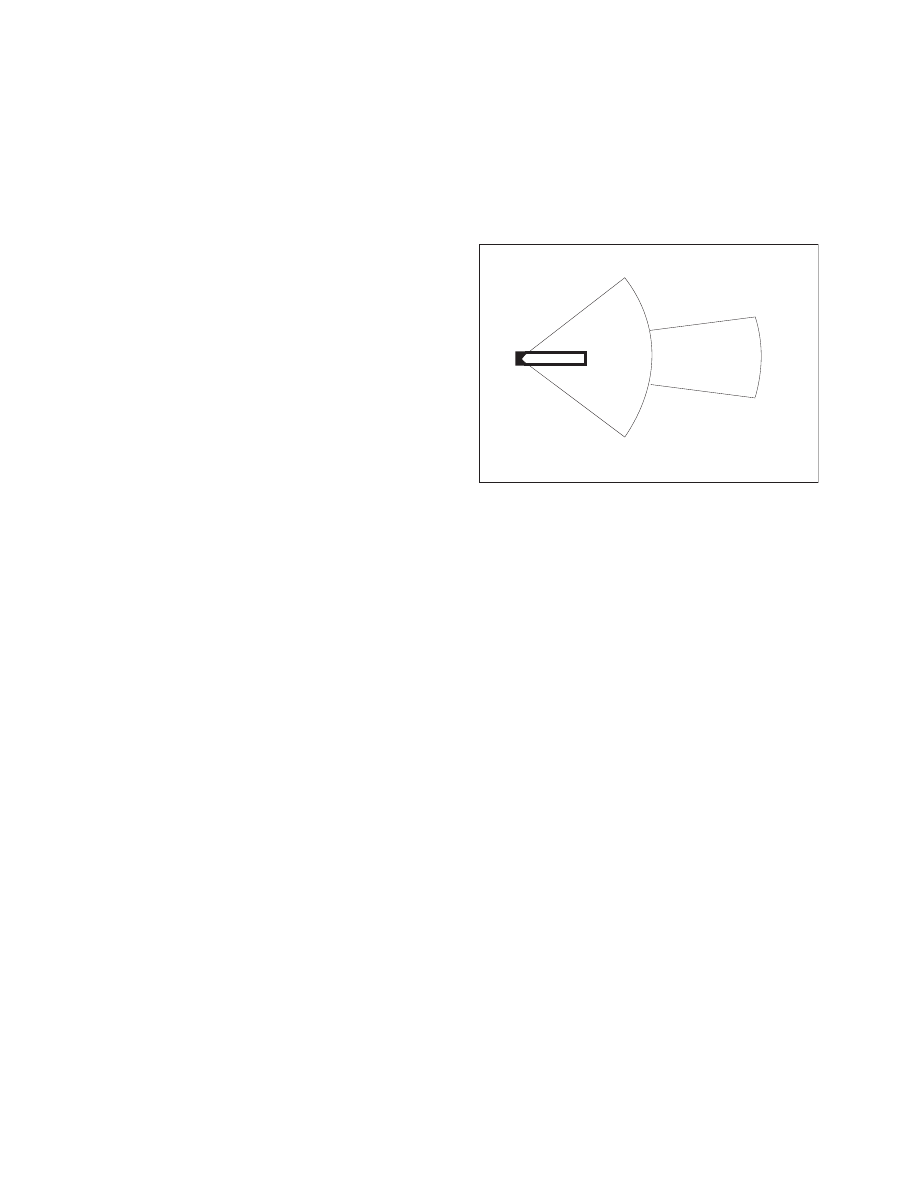
5.
The localizer provides course guidance
throughout the descent path to the runway threshold
from a distance of 18 NM from the antenna between
an altitude of 1,000 feet above the highest terrain
along the course line and 4,500 feet above the
elevation of the antenna site. Proper off
−
course
indications are provided throughout the following
angular areas of the operational service volume:
(a)
To 10 degrees either side of the course
along a radius of 18 NM from the antenna; and
(b)
From 10 to 35 degrees either side of the
course along a radius of 10 NM. (See FIG 1
−
1
−
6.)
FIG 1
−
1
−
6
Limits of Localizer Coverage
RUNWAY
RUNWAY
LOCALIZER
ANTENNA
LOCALIZER
ANTENNA
10 NM10
N
M
18 NM18
N
M
NORMAL LIMITS OF LOCALIZER
COVERAGE: THE SAME AREA
APPLIES TO A BACK COURSE
WHEN PROVIDED.
NORMAL LIMITS OF LOCALIZER
COVERAGE: THE SAME AREA
APPLIES TO A BACK COURSE
WHEN PROVIDED.
10°
10°
35°
35°
6.
Unreliable signals may be received outside
these areas.
c. Localizer Type Directional Aid (LDA)
1.
The LDA is of comparable use and accuracy
to a localizer but is not part of a complete ILS. The
LDA course usually provides a more precise
approach course than the similar Simplified
Directional Facility (SDF) installation, which may
have a course width of 6 or 12 degrees.
2.
The LDA is not aligned with the runway.
Straight
−
in minimums may be published where
alignment does not exceed 30 degrees between the
course and runway. Circling minimums only are
published where this alignment exceeds 30 degrees.
3.
A very limited number of LDA approaches
also incorporate a glideslope. These are annotated in
the plan view of the instrument approach chart with
a note, “LDA/Glideslope.” These procedures fall
under a newly defined category of approaches called
Approach with Vertical Guidance (APV) described in
paragraph 5
−
4
−
5, Instrument Approach Procedure
Charts, subparagraph a7(b), Approach with Vertical
Guidance (APV). LDA minima for with and without
glideslope is provided and annotated on the minima
lines of the approach chart as S
−
LDA/GS and
S
−
LDA. Because the final approach course is not
aligned with the runway centerline, additional
maneuvering will be required compared to an ILS
approach.