AIM
8/15/19
2
−
1
−
5
Airport Lighting Aids
2.
When the aircraft descends from green to red, the pilot may see a dark amber color during the transition from green to
red.
FIG 2
−
1
−
7
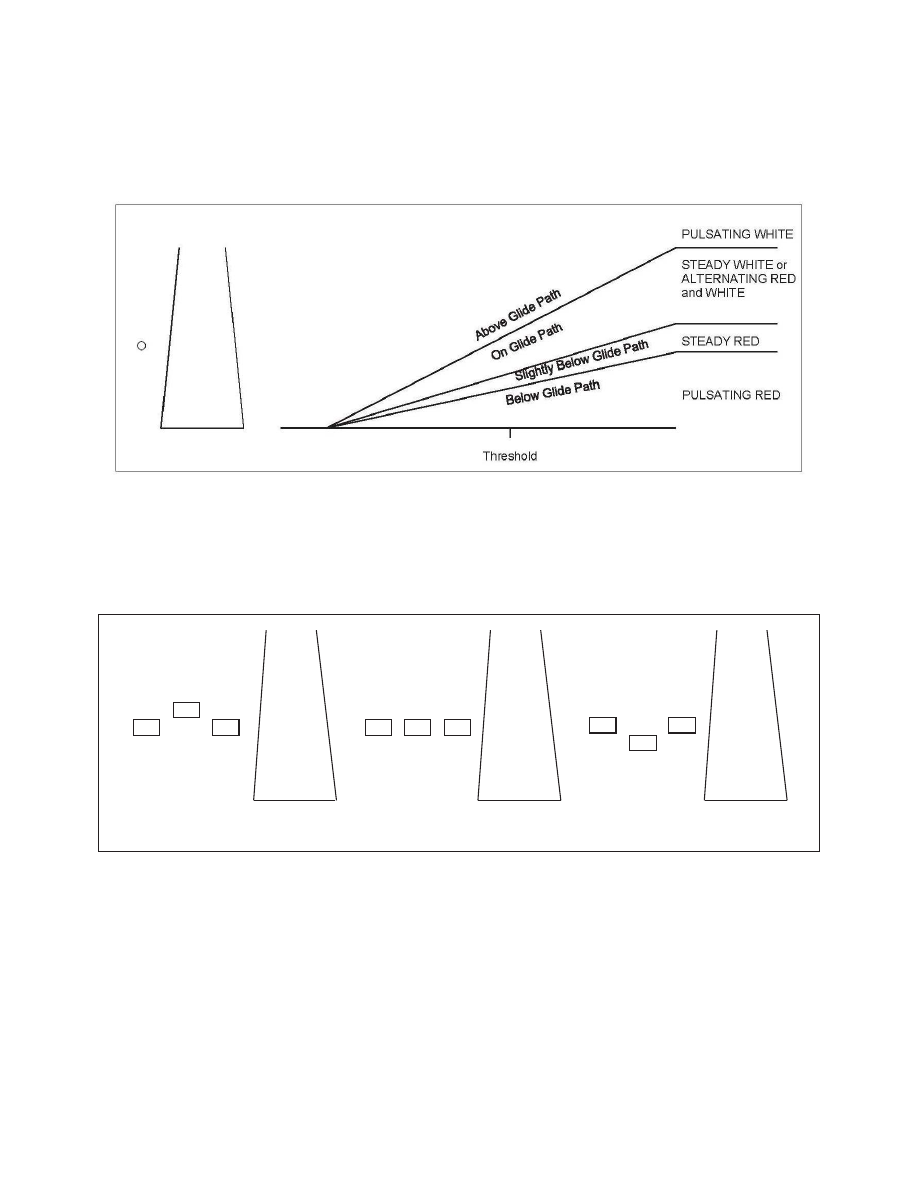
Pulsating Visual Approach Slope Indicator
NOTE
−
Since the PVASI consists of a single light source which could possibly be confused with other light sources, pilots should
exercise care to properly locate and identify the light signal.
FIG 2
−
1
−
8
Alignment of Elements
Below Glide Path
On Glide Path
Above Glide Path
d. Pulsating Systems.
Pulsating visual ap-
proach slope indicators normally consist of a single
light unit projecting a two
−
color visual approach
path into the final approach area of the runway upon
which the indicator is installed. The on glide path
indication may be a steady white light or alternating
RED and WHITE light. The slightly below glide path
indication is a steady red light. If the aircraft descends
further below the glide path, the red light starts to
pulsate. The above glide path indication is a pulsating
white light. The pulsating rate increases as the aircraft
gets further above or below the desired glide slope.
The useful range of the system is about four miles
during the day and up to ten miles at night. (See
FIG 2
−
1
−
7.)
e. Alignment of Elements Systems.
Alignment
of elements systems are installed on some small
general aviation airports and are a low
−
cost system
consisting of painted plywood panels, normally black
and white or fluorescent orange. Some of these
systems are lighted for night use. The useful range of