AIM
8/15/19
2
−
3
−
3
Airport Marking Aids and Signs
FIG 2
−
3
−
2
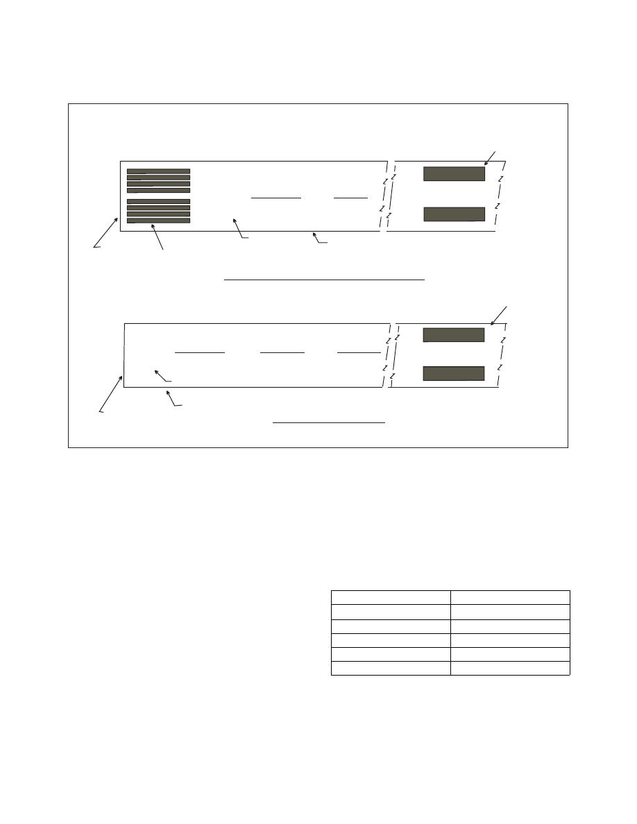
Nonprecision Instrument Runway and Visual Runway Markings
20
20
AIMING POINT
MARKING
THRESHOLD THRESHOLD
MARKINGS
DESIGNATION
MARKING
PAVEMENT EDGE
AIMING POINT
MARKING
PAVEMENT EDGE
DESIGNATION MARKING
THRESHOLD
NONPRECISION INSTRUMENT RUNWAY MARKINGS
VISUAL RUNWAY MARKINGS
f. Runway Side Stripe Marking.
Runway side
stripes delineate the edges of the runway. They
provide a visual contrast between runway and the
abutting terrain or shoulders. Side stripes consist of
continuous white stripes located on each side of the
runway as shown in FIG 2
−
3
−
4.
g. Runway Shoulder Markings.
Runway shoul-
der stripes may be used to supplement runway side
stripes to identify pavement areas contiguous to the
runway sides that are not intended for use by aircraft.
Runway shoulder stripes are yellow.
(See FIG 2
−
3
−
5.)
h. Runway Threshold Markings.
Runway
threshold markings come in two configurations. They
either consist of eight longitudinal stripes of uniform
dimensions disposed symmetrically about the
runway centerline (as shown in FIG 2
−
3
−
1) or the
number of stripes is related to the runway width as
indicated in TBL 2
−
3
−
2. A threshold marking helps
identify the beginning of the runway that is available
for landing. In some instances, the landing threshold
may be relocated or displaced.
TBL 2
−
3
−
2
Number of Runway Threshold Stripes
Runway Width
Number of Stripes
60 feet (18 m)
4
75 feet (23 m)
6
100 feet (30 m)
8
150 feet (45 m)
12
200 feet (60 m)
16