220
14 CFR Ch. I (1–1–19 Edition)
§ 25.143
(2) During an approach and go-
around; and
(3) During an approach and landing.
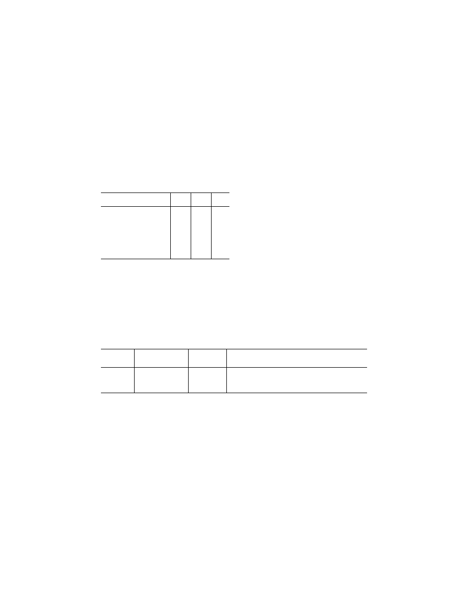
(d) The following table prescribes, for
conventional wheel type controls, the
maximum control forces permitted
during the testing required by para-
graph (a) through (c) of this section:
Force, in pounds, applied to the
control wheel or rudder pedals
Pitch Roll Yaw
For short term application for
pitch and roll control—two
hands available for control ....
75
50
For short term application for
pitch and roll control—one
hand available for control ......
50
25
For short term application for
yaw control .............................
150
For long term application ..........
10
5
20
(e) Approved operating procedures or
conventional operating practices must
be followed when demonstrating com-
pliance with the control force limita-
tions for short term application that
are prescribed in paragraph (d) of this
section. The airplane must be in trim,
or as near to being in trim as practical,
in the preceding steady flight condi-
tion. For the takeoff condition, the air-
plane must be trimmed according to
the approved operating procedures.
(f) When demonstrating compliance
with the control force limitations for
long term application that are pre-
scribed in paragraph (d) of this section,
the airplane must be in trim, or as near
to being in trim as practical.
(g) When maneuvering at a constant
airspeed or Mach number (up to V
FC
/
M
FC
), the stick forces and the gradient
of the stick force versus maneuvering
load factor must lie within satisfactory
limits. The stick forces must not be so
great as to make excessive demands on
the pilot’s strength when maneuvering
the airplane, and must not be so low
that the airplane can easily be over-
stressed inadvertently. Changes of gra-
dient that occur with changes of load
factor must not cause undue difficulty
in maintaining control of the airplane,
and local gradients must not be so low
as to result in a danger of overcontrol-
ling.
(h) The maneuvering capabilities in a
constant speed coordinated turn at for-
ward center of gravity, as specified in
the following table, must be free of
stall warning or other characteristics
that might interfere with normal ma-
neuvering:
Configuration Speed
Maneuvering
bank angle in a
coordinated turn
Thrust/power setting
Takeoff ..........
V
2
30
°
Asymmetric WAT-Limited.
1
Takeoff ..........
2
V
2
+ XX
40
°
All-engines-operating climb.
3
En route ........
V
FTO
40
°
Asymmetric WAT-Limited.
1
Landing .........
V
REF
40
°
Symmetric for
¥
3
°
flight path angle.
1
A combination of weight, altitude, and temperature (WAT) such that the thrust or power setting produces the minimum climb
gradient specified in § 25.121 for the flight condition.
2
Airspeed approved for all-engines-operating initial climb.
3
That thrust or power setting which, in the event of failure of the critical engine and without any crew action to adjust the thrust
or power of the remaining engines, would result in the thrust or power specified for the takeoff condition at V
2
, or any lesser
thrust or power setting that is used for all-engines-operating initial climb procedures.
(i) When demonstrating compliance
with § 25.143 in icing conditions—
(1) Controllability must be dem-
onstrated with the most critical of the
ice accretion(s) for the particular
flight phase as defined in Appendices C
and O of this part, as applicable, in ac-
cordance with § 25.21(g);
(2) It must be shown that a push force
is required throughout a pushover ma-
neuver down to a zero g load factor, or
the lowest load factor obtainable if
limited by elevator power or other de-
sign characteristic of the flight control
system. It must be possible to prompt-
ly recover from the maneuver without
exceeding a pull control force of 50
pounds; and
(3) Any changes in force that the
pilot must apply to the pitch control to
maintain speed with increasing sideslip
angle must be steadily increasing with
no force reversals, unless the change in
control force is gradual and easily con-
trollable by the pilot without using ex-
ceptional piloting skill, alertness, or
strength.
(j) For flight in icing conditions be-
fore the ice protection system has been
VerDate Sep<11>2014
12:50 Apr 30, 2019
Jkt 247046
PO 00000
Frm 00230
Fmt 8010
Sfmt 8010
Y:\SGML\247046.XXX
247046
spaschal on DSK3GDR082PROD with CFR