254
14 CFR Ch. I (1–1–19 Edition)
§ 25.511
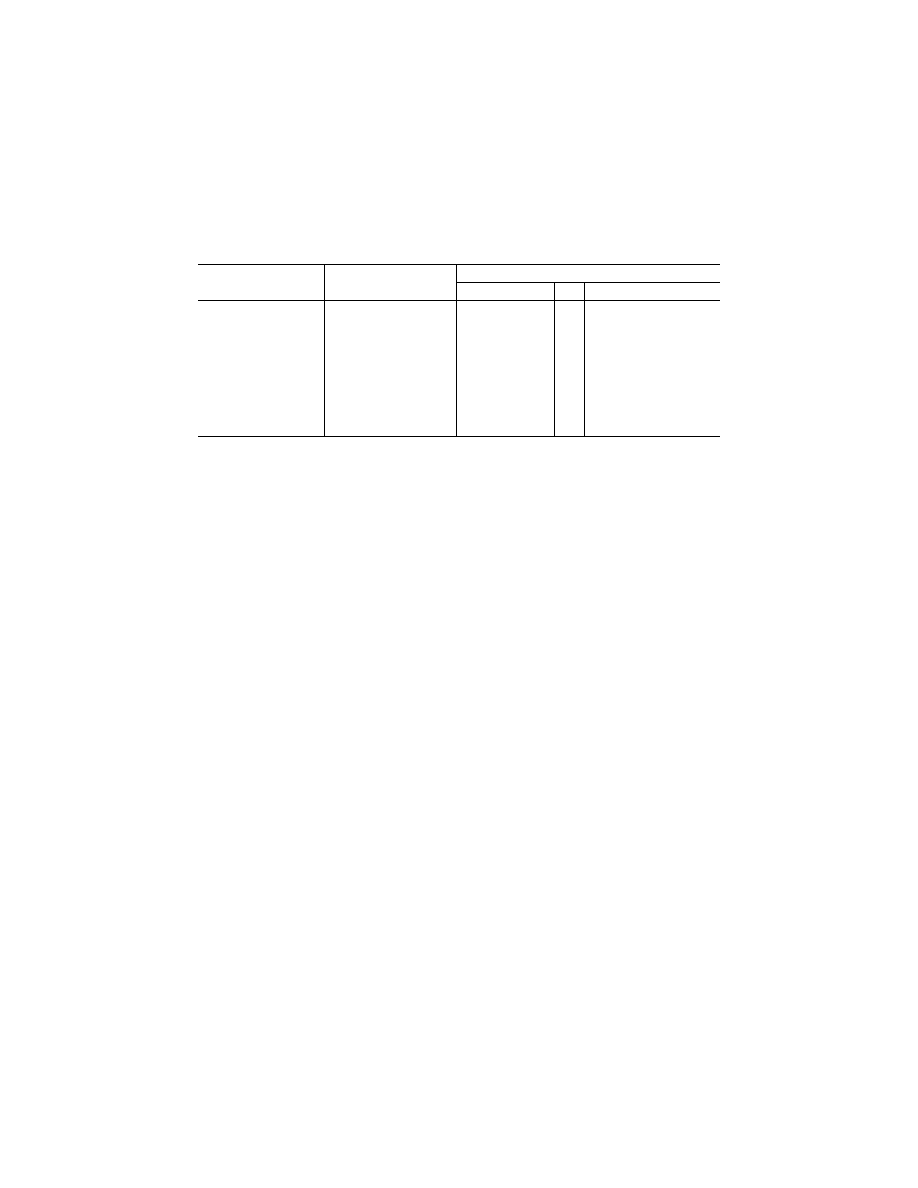
Tow point
Position
Load
Magnitude No.
Direction
Main gear ...............................
................................................
0.75
F
TOW
per main
gear unit.
1
2
3
4
Forward, parallel to drag axis.
Forward, at 30
°
to drag axis.
Aft, parallel to drag axis.
Aft, at 30
°
to drag axis.
Auxiliary gear .........................
Swiveled forward ....................
1.0
F
TOW
...................
5
6
Forward.
Aft.
Swiveled aft ............................
......do .......................
7
8
Forward.
Aft.
Swiveled 45
°
from forward .....
0.5
F
TOW
...................
9
10
Forward, in plane of wheel.
Aft, in plane of wheel.
Swiveled 45
°
from aft .............
......do .......................
11
12
Forward, in plane of wheel.
Aft, in plane of wheel.
[Doc. No. 5066, 29 FR 18291, Dec. 24, 1964, as amended by Amdt. 25–23, 35 FR 5673, Apr. 8, 1970]
§ 25.511
Ground load: unsymmetrical
loads on multiple-wheel units.
(a)
General.
Multiple-wheel landing
gear units are assumed to be subjected
to the limit ground loads prescribed in
this subpart under paragraphs (b)
through (f) of this section. In addi-
tion—
(1) A tandem strut gear arrangement
is a multiple-wheel unit; and
(2) In determining the total load on a
gear unit with respect to the provisions
of paragraphs (b) through (f) of this
section, the transverse shift in the load
centroid, due to unsymmetrical load
distribution on the wheels, may be ne-
glected.
(b)
Distribution of limit loads to wheels;
tires inflated.
The distribution of the
limit loads among the wheels of the
landing gear must be established for
each landing, taxiing, and ground han-
dling condition, taking into account
the effects of the following factors:
(1) The number of wheels and their
physical arrangements. For truck type
landing gear units, the effects of any
seesaw motion of the truck during the
landing impact must be considered in
determining the maximum design loads
for the fore and aft wheel pairs.
(2) Any differentials in tire diameters
resulting from a combination of manu-
facturing tolerances, tire growth, and
tire wear. A maximum tire-diameter
differential equal to
2
⁄
3
of the most un-
favorable combination of diameter
variations that is obtained when tak-
ing into account manufacturing toler-
ances, tire growth, and tire wear, may
be assumed.
(3) Any unequal tire inflation pres-
sure, assuming the maximum variation
to be
±
5 percent of the nominal tire in-
flation pressure.
(4) A runway crown of zero and a run-
way crown having a convex upward
shape that may be approximated by a
slope of 1
1
⁄
2
percent with the hori-
zontal. Runway crown effects must be
considered with the nose gear unit on
either slope of the crown.
(5) The airplane attitude.
(6) Any structural deflections.
(c)
Deflated tires.
The effect of de-
flated tires on the structure must be
considered with respect to the loading
conditions specified in paragraphs (d)
through (f) of this section, taking into
account the physical arrangement of
the gear components. In addition—
(1) The deflation of any one tire for
each multiple wheel landing gear unit,
and the deflation of any two critical
tires for each landing gear unit using
four or more wheels per unit, must be
considered; and
(2) The ground reactions must be ap-
plied to the wheels with inflated tires
except that, for multiple-wheel gear
units with more than one shock strut,
a rational distribution of the ground
reactions between the deflated and in-
flated tires, accounting for the dif-
ferences in shock strut extensions re-
sulting from a deflated tire, may be
used.
(d)
Landing conditions.
For one and
for two deflated tires, the applied load
to each gear unit is assumed to be 60
percent and 50 percent, respectively, of
the limit load applied to each gear for
VerDate Sep<11>2014
12:50 Apr 30, 2019
Jkt 247046
PO 00000
Frm 00264
Fmt 8010
Sfmt 8010
Y:\SGML\247046.XXX
247046
spaschal on DSK3GDR082PROD with CFR