256
14 CFR Ch. I (1–1–19 Edition)
§ 25.525
maximum design loads for each part of
the seaplane structure.
[Doc. No. 5066, 29 FR 18291, Dec. 24, 1964, as
amended by Amdt. 25–23, 35 FR 5673, Apr. 8,
1970]
§ 25.525
Application of loads.
(a) Unless otherwise prescribed, the
seaplane as a whole is assumed to be
subjected to the loads corresponding to
the load factors specified in § 25.527.
(b) In applying the loads resulting
from the load factors prescribed in
§ 25.527, the loads may be distributed
over the hull or main float bottom (in
order to avoid excessive local shear
loads and bending moments at the lo-
cation of water load application) using
pressures not less than those pre-
scribed in § 25.533(b).
(c) For twin float seaplanes, each
float must be treated as an equivalent
hull on a fictitious seaplane with a
weight equal to one-half the weight of
the twin float seaplane.
(d) Except in the takeoff condition of
§ 25.531, the aerodynamic lift on the
seaplane during the impact is assumed
to be
2
⁄
3
of the weight of the seaplane.
§ 25.527
Hull and main float load fac-
tors.
(a) Water reaction load factors
n
W
must be computed in the following
manner:
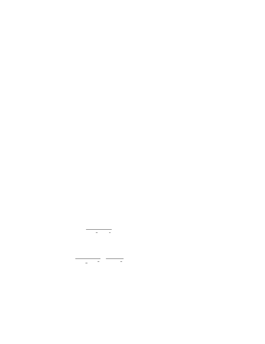
(1) For the step landing case
n
C V
W
w
S
=
⎛
⎝
⎞
⎠
1
0
2
2
3
1
3
Tan
β
(2) For the bow and stern landing
cases
n
C V
W
K
r
w
S
x
=
⎛
⎝
⎞
⎠
×
+
(
)
1
0
1
2
2
2
3
1
3
2
3
1
Tan
β
(b) The following values are used:
(1)
n
W
= water reaction load factor
(that is, the water reaction divided by
seaplane weight).
(2)
C
1
= empirical seaplane operations
factor equal to 0.012 (except that this
factor may not be less than that nec-
essary to obtain the minimum value of
step load factor of 2.33).
(3)
V
S
0
= seaplane stalling speed in
knots with flaps extended in the appro-
priate landing position and with no
slipstream effect.
(4)
b
= angle of dead rise at the longi-
tudinal station at which the load fac-
tor is being determined in accordance
with figure 1 of appendix B.
(5)
W=
seaplane design landing
weight in pounds.
(6)
K
1
= empirical hull station weigh-
ing factor, in accordance with figure 2
of appendix B.
(7)
r
x
= ratio of distance, measured
parallel to hull reference axis, from the
center of gravity of the seaplane to the
hull longitudinal station at which the
load factor is being computed to the ra-
dius of gyration in pitch of the sea-
plane, the hull reference axis being a
straight line, in the plane of sym-
metry, tangential to the keel at the
main step.
(c) For a twin float seaplane, because
of the effect of flexibility of the attach-
ment of the floats to the seaplane, the
factor
K
1
may be reduced at the bow
and stern to 0.8 of the value shown in
figure 2 of appendix B. This reduction
applies only to the design of the carry-
through and seaplane structure.
[Doc. No. 5066, 29 FR 18291, Dec. 24, 1964, as
amended by Amdt. 25–23, 35 FR 5673, Apr. 8,
1970]
§ 25.529
Hull and main float landing
conditions.
(a)
Symmetrical step, bow, and stern
landing.
For symmetrical step, bow,
and stern landings, the limit water re-
action load factors are those computed
under § 25.527. In addition—
(1) For symmetrical step landings,
the resultant water load must be ap-
plied at the keel, through the center of
gravity, and must be directed per-
pendicularly to the keel line;
(2) For symmetrical bow landings,
the resultant water load must be ap-
plied at the keel, one-fifth of the longi-
tudinal distance from the bow to the
step, and must be directed perpendicu-
larly to the keel line; and
(3) For symmetrical stern landings,
the resultant water load must be ap-
plied at the keel, at a point 85 percent
of the longitudinal distance from the
step to the stern post, and must be di-
rected perpendicularly to the keel line.
VerDate Sep<11>2014
12:50 Apr 30, 2019
Jkt 247046
PO 00000
Frm 00266
Fmt 8010
Sfmt 8010
Y:\SGML\247046.XXX
247046
EC28SE91.036</MATH>
EC28SE91.037</MATH>
spaschal on DSK3GDR082PROD with CFR