257
Federal Aviation Administration, DOT
§ 25.533
(b)
Unsymmetrical landing for hull and
single float seaplanes.
Unsymmetrical
step, bow, and stern landing conditions
must be investigated. In addition—
(1) The loading for each condition
consists of an upward component and a
side component equal, respectively, to
0.75 and 0.25 tan
b
times the resultant
load in the corresponding symmetrical
landing condition; and
(2) The point of application and di-
rection of the upward component of the
load is the same as that in the sym-
metrical condition, and the point of ap-
plication of the side component is at
the same longitudinal station as the
upward component but is directed in-
ward perpendicularly to the plane of
symmetry at a point midway between
the keel and chine lines.
(c)
Unsymmetrical landing; twin float
seaplanes.
The unsymmetrical loading
consists of an upward load at the step
of each float of 0.75 and a side load of
0.25 tan
b
at one float times the step
landing load reached under § 25.527. The
side load is directed inboard, per-
pendicularly to the plane of symmetry
midway between the keel and chine
lines of the float, at the same longitu-
dinal station as the upward load.
§ 25.531
Hull and main float takeoff
condition.
For the wing and its attachment to
the hull or main float—
(a) The aerodynamic wing lift is as-
sumed to be zero; and
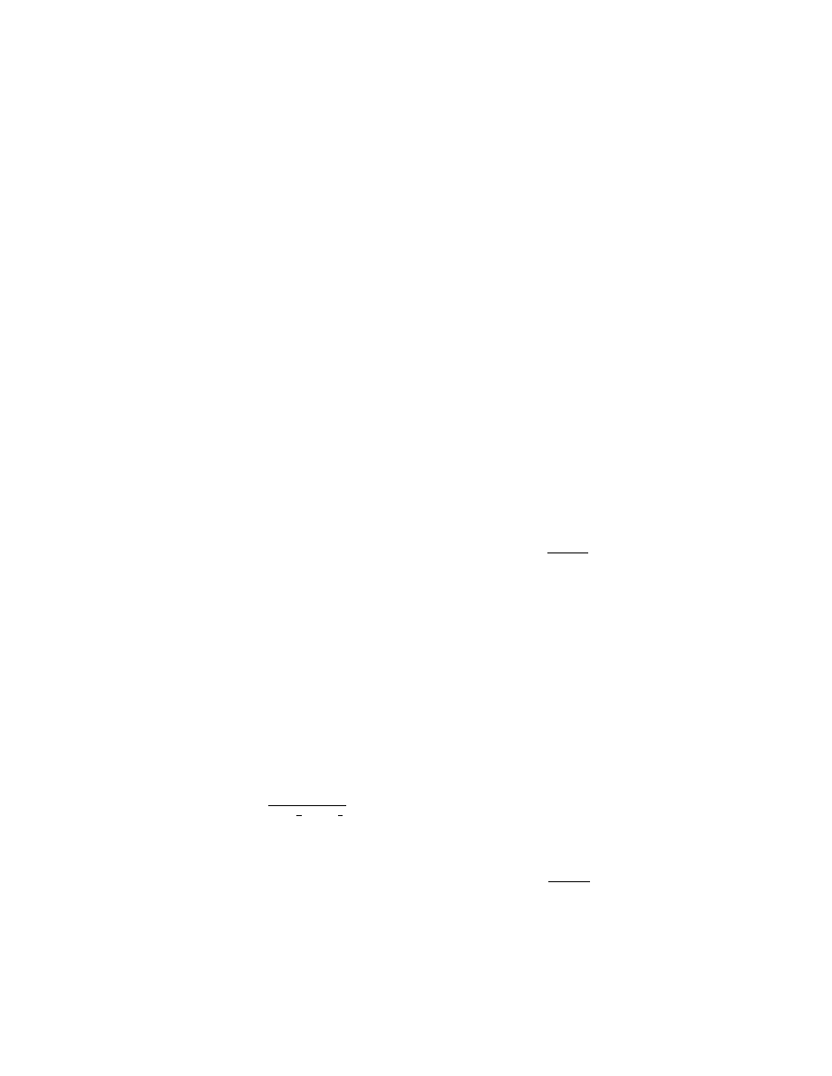
(b) A downward inertia load, cor-
responding to a load factor computed
from the following formula, must be
applied:
n
C
V
W
TO
S
=
⎛
⎝
⎞
⎠
1
2
2
3
1
3
tan
β
where—
n
= inertia load factor;
C
TO
= empirical seaplane operations factor
equal to 0.004;
V
S
1
= seaplane stalling speed (knots) at the
design takeoff weight with the flaps ex-
tended in the appropriate takeoff posi-
tion;
b
= angle of dead rise at the main step (de-
grees); and
W
= design water takeoff weight in pounds.
[Doc. No. 5066, 29 FR 18291, Dec. 24, 1964, as
amended by Amdt. 25–23, 35 FR 5673, Apr. 8,
1970]
§ 25.533
Hull and main float bottom
pressures.
(a)
General.
The hull and main float
structure, including frames and bulk-
heads, stringers, and bottom plating,
must be designed under this section.
(b)
Local pressures.
For the design of
the bottom plating and stringers and
their attachments to the supporting
structure, the following pressure dis-
tributions must be applied:
(1) For an unflared bottom, the pres-
sure at the chine is 0.75 times the pres-
sure at the keel, and the pressures be-
tween the keel and chine vary linearly,
in accordance with figure 3 of appendix
B. The pressure at the keel (psi) is
computed as follows:
P
C
K V
k
S
k
=
×
2
2
1
2
tan
β
where—
P
k
= pressure (p.s.i.) at the keel;
C
2
= 0.00213;
K
2
= hull station weighing factor, in accord-
ance with figure 2 of appendix B;
V
S
1
= seaplane stalling speed (Knots) at the
design water takeoff weight with flaps
extended in the appropriate takeoff posi-
tion; and
b
K
= angle of dead rise at keel, in accordance
with figure 1 of appendix B.
(2) For a flared bottom, the pressure
at the beginning of the flare is the
same as that for an unflared bottom,
and the pressure between the chine and
the beginning of the flare varies lin-
early, in accordance with figure 3 of ap-
pendix B. The pressure distribution is
the same as that prescribed in para-
graph (b)(1) of this section for an
unflared bottom except that the pres-
sure at the chine is computed as fol-
lows:
P
C
K V
ch
S
=
×
3
2
1
2
tan
β
where—
P
ch
= pressure (p.s.i.) at the chine;
C
3
= 0.0016;
K
2
= hull station weighing factor, in accord-
ance with figure 2 of appendix B;
VerDate Sep<11>2014
12:50 Apr 30, 2019
Jkt 247046
PO 00000
Frm 00267
Fmt 8010
Sfmt 8010
Y:\SGML\247046.XXX
247046
EC28SE91.038</MATH>
EC28SE91.039</MATH>
EC28SE91.040</MATH>
spaschal on DSK3GDR082PROD with CFR