570
14 CFR Ch. I (1–1–19 Edition)
Pt. 27, App. D
29.45(a) and (b)(2)—General.
29.49(a)—Performance at minimum operating
speed.
29.51—Takeoff data: General.
29.53—Takeoff: Category A.
29.55—Takeoff decision point: Category A.
29.59—Takeoff Path: Category A.
29.60—Elevated heliport takeoff path: Cat-
egory A.
29.61—Takeoff distance: Category A.
29.62—Rejected takeoff: Category A.
29.64—Climb: General.
29.65(a)—Climb: AEO.
29.67(a)—Climb: OEI.
29.75—Landing: General.
29.77—Landing decision point: Category A.
29.79—Landing: Category A.
29.81—Landing distance (Ground level sites):
Category A.
29.85—Balked landing: Category A.
29.87(a)—Height-velocity envelope.
29.547(a) and (b)—Main and tail rotor struc-
ture.
29.861(a)—Fire protection of structure, con-
trols, and other parts.
29.901(c)—Powerplant: Installation.
29.903(b) (c) and (e)—Engines.
29.908(a)—Cooling fans.
29.917(b) and (c)(1)—Rotor drive system: De-
sign.
29.927(c)(1)—Additional tests.
29.953(a)—Fuel system independence.
29.1027(a)—Transmission and gearboxes: Gen-
eral.
29.1045(a)(1), (b), (c), (d), and (f)—Climb cool-
ing test procedures.
29.1047(a)—Takeoff cooling test procedures.
29.1181(a)—Designated fire zones: Regions in-
cluded.
29.1187(e)—Drainage and ventilation of fire
zones.
29.1189(c)—Shutoff means.
29.1191(a)(1)—Firewalls.
29.1193(e)—Cowling and engine compartment
covering.
29.1195(a) and (d)—Fire extinguishing sys-
tems (one shot).
29.1197—Fire extinguishing agents.
29.1199—Extinguishing agent containers.
29.1201—Fire extinguishing system materials.
29.1305(a) (6) and (b)—Powerplant instru-
ments.
29.1309(b)(2) (i) and (d)—Equipment, systems,
and installations.
29.1323(c)(1)—Airspeed indicating system.
29.1331(b)—Instruments using a power supply.
29.1351(d)(2)—Electrical systems and equip-
ment: General (operation without normal
electrical power).
29.1587(a)—Performance information.
N
OTE
: In complying with the paragraphs
listed in paragraph C27.2 above, relevant ma-
terial in the AC ‘‘Certification of Transport
Category Rotorcraft’’ should be used.
[Doc. No. 28008, 61 FR 21907, May 10, 1996]
A
PPENDIX
D
TO
P
ART
27—HIRF E
NVI
-
RONMENTS
AND
E
QUIPMENT
HIRF
T
EST
L
EVELS
This appendix specifies the HIRF environ-
ments and equipment HIRF test levels for
electrical and electronic systems under
§ 27.1317. The field strength values for the
HIRF environments and laboratory equip-
ment HIRF test levels are expressed in root-
mean-square units measured during the peak
of the modulation cycle.
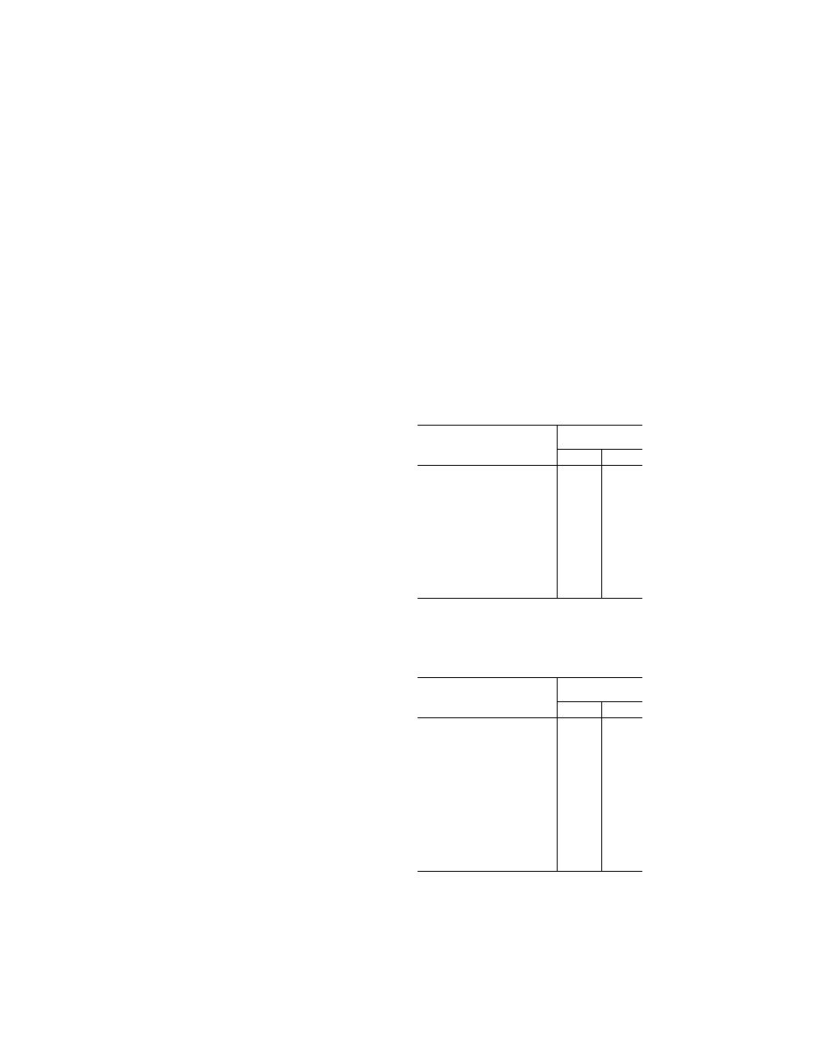
(a) HIRF environment I is specified in the
following table:
T
ABLE
I.—HIRF E
NVIRONMENT
I
Frequency
Field strength
(volts/meter)
Peak Average
10 kHz–2 MHz ...................................
50
50
2 MHz–30 MHz .................................
100
100
30 MHz–100 MHz .............................
50
50
100 MHz–400 MHz ...........................
100
100
400 MHz–700 MHz ...........................
700
50
700 MHz–1 GHz ................................
700
100
1 GHz–2 GHz ....................................
2,000
200
2 GHz–6 GHz ....................................
3,000
200
6 GHz–8 GHz ....................................
1,000
200
8 GHz–12 GHz ..................................
3,000
300
12 GHz–18 GHz ................................
2,000
200
18 GHz–40 GHz ................................
600
200
In this table, the higher field strength applies at the fre-
quency band edges.
(b) HIRF environment II is specified in the
following table:
T
ABLE
II.—HIRF E
NVIRONMENT
II
Frequency
Field strength
(volts/meter)
Peak Average
10 kHz–500 kHz ................................
20
20
500 kHz–2 MHz .................................
30
30
2 MHz–30 MHz .................................
100
100
30 MHz–100 MHz .............................
10
10
100 MHz–200 MHz ...........................
30
10
200 MHz–400 MHz ...........................
10
10
400 MHz–1 GHz ................................
700
40
1 GHz–2 GHz ....................................
1,300
160
2 GHz–4 GHz ....................................
3,000
120
4 GHz–6 GHz ....................................
3,000
160
6 GHz–8 GHz ....................................
400
170
8 GHz–12 GHz ..................................
1,230
230
12 GHz–18 GHz ................................
730
190
18 GHz–40 GHz ................................
600
150
In this table, the higher field strength applies at the fre-
quency band edges.
(c) HIRF environment III is specified in the
following table:
VerDate Sep<11>2014
12:50 Apr 30, 2019
Jkt 247046
PO 00000
Frm 00580
Fmt 8010
Sfmt 8002
Y:\SGML\247046.XXX
247046
spaschal on DSK3GDR082PROD with CFR