801
Federal Aviation Administration, DOT
Pt. 36, App. A
(1) The term 0.01[
a
(i)
¥
a
(i)
0
]QK is the ad-
justment for the effect of the change in
sound attenuation coefficient, and
a
(i) and
a
(i)
0
are the coefficients for the test and ref-
erence atmospheric conditions respectively,
determined under section A36.7 of this appen-
dix;
(2) The term 0.01
a
(i)
0
(QK
¥
Q
r
K
r
) is the ad-
justment for the effect of the change in the
noise path length on the sound attenuation;
(3) The term 20 log(QK/Q
r
K
r
) is the adjust-
ment for the effect of the change in the noise
path length due to the inverse square law;
(4) QK and Q
r
K
r
are measured in meters and
a
(i) and
a
(i)
0
are expressed in dB/100 m.
A36.9.3.2.1.1
PNLT Correction.
(a) Convert the corrected values, SPL(i)
r
,
to PNLT
r
;
(b) Calculate the correction term
D
1
using
the following equation:
D
1
= PNLT
r
¥
PNLTM
A36.9.3.2.1.2 Add
D
1
arithmetically to the
EPNL calculated from the measured data.
A36.9.3.2.2 If, during a test flight, several
peak values of PNLT that are within 2 dB of
PNLTM are observed, the procedure defined
in section A36.9.3.2.1 must be applied at each
peak, and the adjustment term, calculated
according to section A36.9.3.2.1, must be
added to each peak to give corresponding ad-
justed peak values of PNLT. If these peak
values exceed the value at the moment of
PNLTM, the maximum value of such exceed-
ance must be added as a further adjustment
to the EPNL calculated from the measured
data.
A36.9.3.3
Adjustments to duration correction.
A36.9.3.3.1 Whenever the measured flight
paths and/or the ground velocities of the test
conditions differ from the reference flight
paths and/or the ground velocities of the ref-
erence conditions, duration adjustments
must be applied to the EPNL values cal-
culated from the measured data. The adjust-
ments must be calculated as described below.
A36.9.3.3.2 For the flight path shown in Fig-
ure A36–6, the adjustment term is calculated
as follows:
D
2
=
¥
7.5 log(QK/Q
r
K
r
) + 10 log(V/V
r
)
(a) Add
D
2
arithmetically to the EPNL cal-
culated from the measured data.
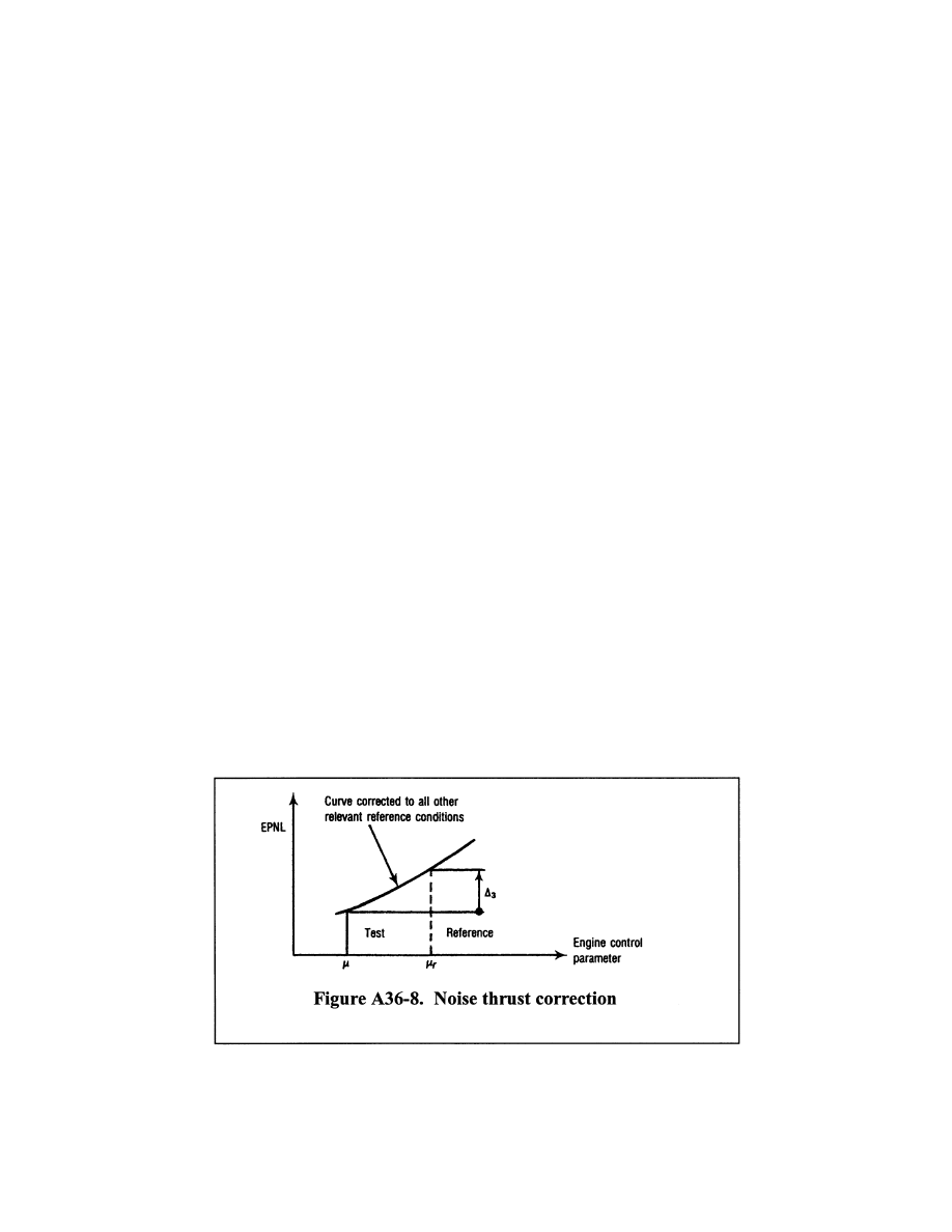
A36.9.3.4
Source noise adjustments.
A36.9.3.4.1 To account for differences be-
tween the parameters affecting engine noise
as measured in the certification flight tests,
and those calculated or specified in the ref-
erence conditions, the source noise adjust-
ment must be calculated and applied. The
adjustment is determined from the manufac-
turer’s data approved by the FAA. Typical
data used for this adjustment are illustrated
in Figure A36–8 that shows a curve of EPNL
versus the engine control parameter
µ
, with
the EPNL data being corrected to all the
other relevant reference conditions (airplane
mass, speed and altitude, air temperature)
and for the difference in noise between the
test engine and the average engine (as de-
fined in section B36.7(b)(7)). A sufficient
number of data points over a range of values
of
µ
r
is required to calculate the source noise
adjustments for lateral, flyover and ap-
proach noise measurements.
A36.9.3.4.2 Calculate adjustment term
D
3
by
subtracting the EPNL value corresponding
to the parameter
µ
from the EPNL value cor-
responding to the parameter
µ
r
. Add
D
3
VerDate Sep<11>2014
12:50 Apr 30, 2019
Jkt 247046
PO 00000
Frm 00811
Fmt 8010
Sfmt 8002
Y:\SGML\247046.XXX
247046
ER08JY02.018</GPH>
spaschal on DSK3GDR082PROD with CFR