146
14 CFR Ch. I (1–1–19 Edition)
Pt. 60, App. A
T
ABLE
A3C—F
UNCTIONS AND
S
UBJECTIVE
T
ESTS
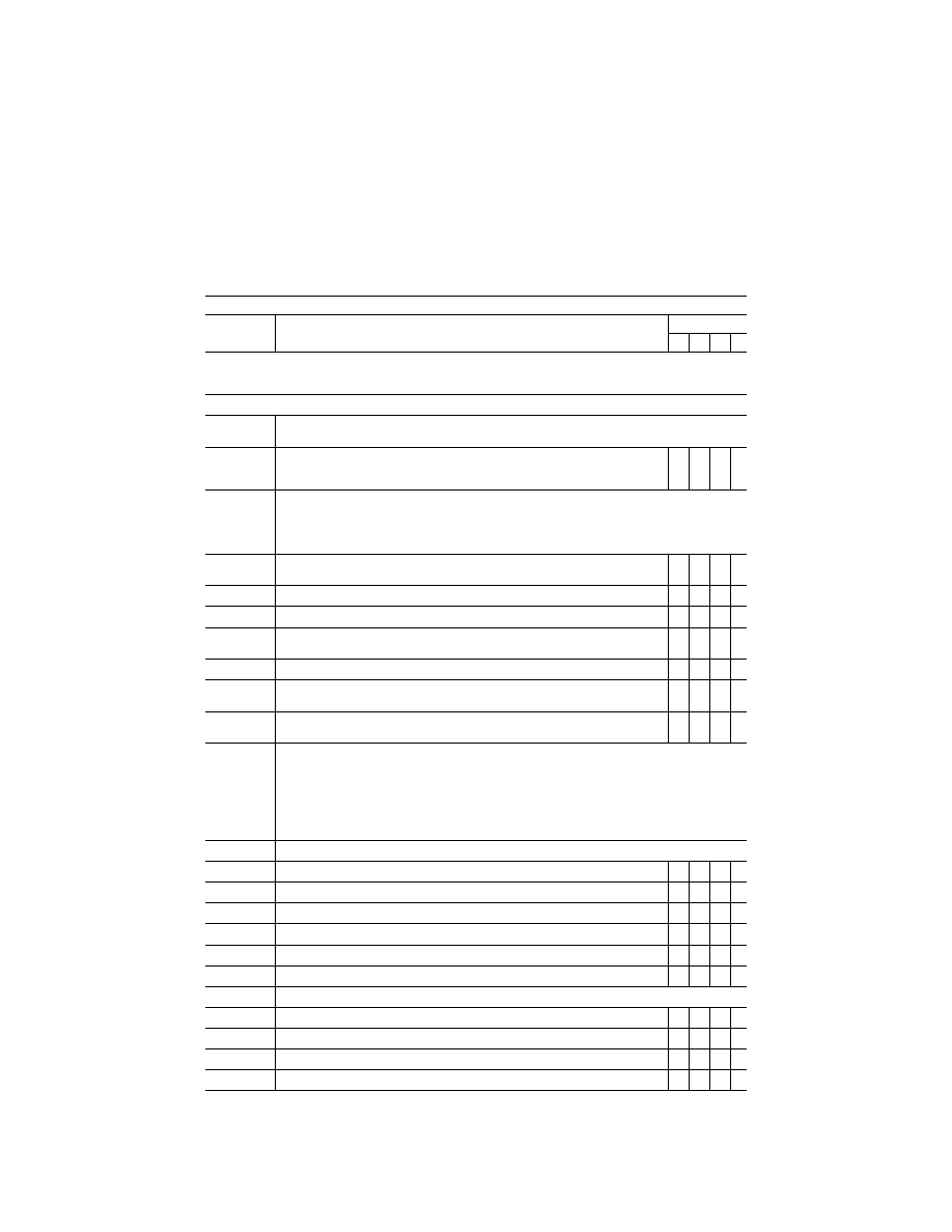
QPS requirements
Entry No.
Additional airport models beyond minimum required for qualification—Class II airport mod-
els
Simulator level
A B C D
This table specifies the minimum airport model content and functionality necessary to add airport models to a simulator’s model
library, beyond those necessary for qualification at the stated level, without the necessity of further involvement of the NSPM
or TPAA.
Begin QPS Requirements
1. ....................
Airport model management. The following is the minimum airport model management requirements for simula-
tors at Levels A, B, C, and D.
1.a. ..........
The direction of strobe lights, approach lights, runway edge lights, visual landing aids, run-
way centerline lights, threshold lights, and touchdown zone lights on the ‘‘in-use’’ runway
must be replicated.
X X X X
2. ....................
Visual feature recognition. The following are the minimum distances at which runway features must be visible
for simulators at Levels A, B, C, and D. Distances are measured from runway threshold to an airplane aligned
with the runway on an extended 3
°
glide-slope in simulated meteorological conditions that recreate the min-
imum distances for visibility. For circling approaches, all requirements of this section apply to the runway used
for the initial approach and to the runway of intended landing.
2.a. ..........
Runway definition, strobe lights, approach lights, and runway edge white lights from 5 sm
(8 km) from the runway threshold.
X X X X
2.b. ..........
Visual Approach Aid lights (VASI or PAPI) from 5 sm (8 km) from the runway threshold .....
X
X
2.c. ..........
Visual Approach Aid lights (VASI or PAPI) from 3 sm (5 km) from the runway threshold .....
X
X
2.d. ..........
Runway centerline lights and taxiway definition from 3 sm (5 km) from the runway thresh-
old.
X X X X
2.e. ..........
Threshold lights and touchdown zone lights from 2 sm (3 km) from the runway threshold ...
X
X
X
X
2.f. ...........
Runway markings within range of landing lights for night scenes and as required by the
surface resolution requirements on day scenes.
X X X X
2.g. ..........
For circling approaches, the runway of intended landing and associated lighting must fade
into view in a non-distracting manner.
X X X X
3. ....................
Airport model content. The following prescribes the minimum requirements for what must be provided in an air-
port model and identifies other aspects of the airport environment that must correspond with that model for sim-
ulators at Levels A, B, C, and D. The detail must be developed using airport pictures, construction drawings
and maps, or other similar data, or developed in accordance with published regulatory material; however, this
does not require that airport models contain details that are beyond the designed capability of the currently
qualified visual system. For circling approaches, all requirements of this section apply to the runway used for
the initial approach and to the runway of intended landing. Only one ‘‘primary’’ taxi route from parking to the
runway end will be required for each ‘‘in-use’’ runway.
3.a. ..........
The surface and markings for each ‘‘in-use’’ runway:
3.a.1. Threshold
markings ..................................................................................................................
X X X X
3.a.2. Runway
numbers ......................................................................................................................
X X X X
3.a.3.
Touchdown zone markings .......................................................................................................
X X X X
3.a.4.
Fixed distance markings ...........................................................................................................
X X X X
3.a.5. Edge
markings ..........................................................................................................................
X X X X
3.a.6. Centerline
stripes ......................................................................................................................
X X X X
3.b. ..........
The lighting for each ‘‘in-use’’ runway
3.b.1. Threshold
lights ........................................................................................................................
X X X X
3.b.2. Edge
lights ................................................................................................................................
X X X X
3.b.3. End
lights ..................................................................................................................................
X X X X
3.b.4. Centerline
lights ........................................................................................................................
X X X X
VerDate Sep<11>2014
16:30 Jun 25, 2019
Jkt 247047
PO 00000
Frm 00156
Fmt 8010
Sfmt 8002
Q:\14\14V2.TXT
PC31
kpayne on VMOFRWIN702 with $$_JOB