396
14 CFR Ch. I (1–1–19 Edition)
Pt. 60, App. C
T
ABLE
C3B—F
UNCTIONS AND
S
UBJECTIVE
T
ESTS
—Continued
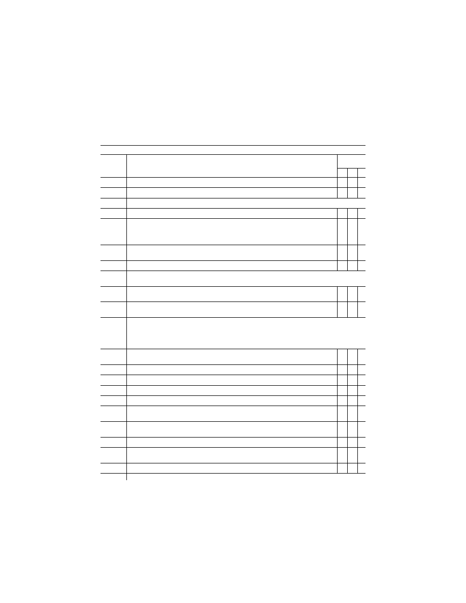
QPS requirements
Entry No.
Visual requirements for qualification at the stated level
class I airport or landing area models
Simulator
level
B C D
2.d.2. ........
Buildings, trees, or other vertical obstructions in the immediate landing area ......................................
X X
2.d.3. ........
Suspended wires in the immediate landing area ...................................................................................
X X
2.e. ...........
Airport applications. Each airport must have the following:
2.e.1. ........
At least one runway designated as ‘‘in-use’’, appropriately marked and capable of being lighted fully
X
X
2.e.2. ........
Runway threshold elevations and locations must be modeled to provide sufficient correlation with
helicopter systems (e.g., HGS, GPS, altimeter). Slopes in runways, taxiways, and ramp areas, if
depicted in the visual scene, may not cause distracting or unrealistic effects, including pilot eye-
point height variation.
X X X
2.e.3. ........
Appropriate approach lighting systems and airfield lighting for a VFR circuit and landing, non-preci-
sion approaches and landings, and precision approaches and landings, as appropriate..
X X
2.e.4. ........
Representative taxiway lights .................................................................................................................
X
3.
..............
Airport or landing area model management
The following is the minimum visual scene management requirements
3.a. ...........
Runway and helicopter landing area approach lighting must fade into view in accordance with the
environmental conditions set in the simulator.
X X X
3.b. ...........
The direction of strobe lights, approach lights, runway edge lights, visual landing aids, runway cen-
terline lights, threshold lights, touchdown zone lights, and TLOF or FATO lights must be replicated.
X X X
4.
..............
Visual feature recognition.
The following are the minimum distances at which runway features must be visible. Distances are measured from
runway threshold or a helicopter landing area to a helicopter aligned with the runway or helicopter landing area on
an extended 3
°
glide-slope in simulated meteorological conditions. For circling approaches, all tests apply to the
runway used for the initial approach and to the runway of intended landing
4.a. ...........
For runways: Runway definition, strobe lights, approach lights, and runway edge lights from 5 sm (8
km) of the runway threshold.
X X X
4.b. ...........
For runways: Centerline lights and taxiway definition from 3 sm (5 km) ...............................................
X X X
4.c. ...........
For runways: Visual Approach Aid lights (VASI or PAPI) from 3 sm (5 km) of the threshold ...............
X
4.d. ...........
For runways: Visual Approach Aid lights (VASI or PAPI) from 5 sm (8 km) of the threshold ...............
X
X
4.e. ...........
For runways: Runway threshold lights and touchdown zone lights from 2 sm (3 km) ..........................
X
X
X
4.f. ............
For runways and helicopter landing areas: Markings within range of landing lights for night/twilight
scenes and the surface resolution test on daylight scenes, as required.
X X X
4.g. ...........
For circling approaches, the runway of intended landing and associated lighting must fade into view
in a non-distracting manner.
X X X
4.h. ...........
For helicopter landing areas: Landing direction lights and raised FATO lights from 1 sm (1.5 km) .....
X
X
X
4.i. ............
For helicopter landing areas: Flush mounted FATO lights, TOFL lights, and the lighted windsock
from 0.5 sm (750 m).
X
4.j. ............
Hover taxiway lighting (yellow/blue/yellow cylinders) from TOFL area ..................................................
X
5.
..............
Airport or helicopter landing area model content
VerDate Sep<11>2014
16:30 Jun 25, 2019
Jkt 247047
PO 00000
Frm 00406
Fmt 8010
Sfmt 8002
Q:\14\14V2.TXT
PC31
kpayne on VMOFRWIN702 with $$_JOB