399
Federal Aviation Administration, DOT
Pt. 60, App. C
T
ABLE
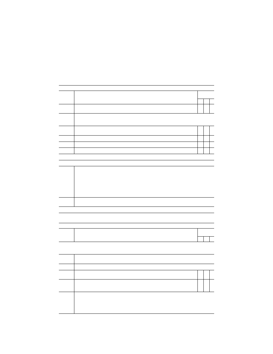
C3B—F
UNCTIONS AND
S
UBJECTIVE
T
ESTS
—Continued
QPS requirements
Entry No.
Visual requirements for qualification at the stated level
class I airport or landing area models
Simulator
level
B C D
8.j. ............
‘‘White-out’’ or ‘‘Brown-out’’ effects due to rotor downwash beginning at a distance above the ground
equal to the rotor diameter.
X
9.
..............
Instructor control of the following:
The following are the minimum instructor controls that must be available in Level B, Level C, and Level D simula-
tors, as indicated.
9.a. ...........
Environmental effects, e.g. cloud base, cloud effects, cloud density, visibility in statute miles/ kilo-
meters and RVR in feet/meters.
X X X
9.b. ...........
Airport or helicopter landing area selection ............................................................................................
X X X
9.c. ...........
Airport or helicopter landing area lighting, including variable intensity ..................................................
X X X
9.d. ...........
Dynamic effects including ground and flight traffic .................................................................................
X X
End QPS Requirement
Begin Information
10.
............
An example of being able to ‘‘combine two airport models to achieve two ‘‘in-use’’ runways: One runway des-
ignated as the ‘‘in-use’’ runway in the first model of the airport, and the second runway designated as the ‘‘in-use’’
runway in the second model of the same airport. For example, the clearance is for the ILS approach to Runway
27, Circle to Land on Runway 18 right. Two airport visual models might be used: the first with Runway 27 des-
ignated as the ‘‘in use’’ runway for the approach to runway 27, and the second with Runway 18 Right designated
as the ‘‘in use’’ runway. When the pilot breaks off the ILS approach to runway 27, the instructor may change to the
second airport visual model in which runway 18 Right is designated as the ‘‘in use’’ runway, and the pilot would
make a visual approach and landing. This process is acceptable to the FAA as long as the temporary interruption
due to the visual model change is not distracting to the pilot.
11.
............
Sponsors are not required to provide every detail of a runway, but the detail that is provided should be correct
within reasonable limits.
End Information
T
ABLE
C3C—F
UNCTIONS AND
S
UBJECTIVE
T
ESTS
QPS requirements
Entry No.
Visual scene content additional airport or landing area models beyond minimum required for quali-
fication
Class II airport or landing area models
Simulator
level
B C D
This table specifies the minimum airport or helicopter landing area visual model content and functionality necessary to add vis-
ual models to a simulator’s visual model library (i.e., beyond those necessary for qualification at the stated level) without the
necessity of further involvement of the NSPM or TPAA.
1.
..............
Airport or landing area model management
The following is the minimum visual scene management requirements for simulators at Levels B, C, and D.
1.a. ...........
The installation and direction of the following lights must be replicated for the ‘‘in-use’’ surface:
1.a.1. ........
For ‘‘in-use’’ runways: Strobe lights, approach lights, runway edge lights, visual landing aids, runway
centerline lights, threshold lights, and touchdown zone lights.
X X X
1.a.2. ........
For ‘‘in-use’’ helicopter landing areas: ground level TLOF perimeter lights, elevated TLOF perimeter
lights (if applicable), Optional TLOF lights (if applicable), ground FATO perimeter lights, elevated
TLOF lights (if applicable), landing direction lights.
X X X
2.
..............
Visual feature recognition
The following are the minimum distances at which runway or landing area features must be visible for simulators at
Levels B, C, and D. Distances are measured from runway threshold or a helicopter landing area to an aircraft
aligned with the runway or helicopter landing area on a 3
°
glide-slope from the aircraft to the touchdown point, in
simulated meteorological conditions. For circling approaches, all tests apply to the runway used for the initial ap-
proach and to the runway of intended landing.
VerDate Sep<11>2014
16:30 Jun 25, 2019
Jkt 247047
PO 00000
Frm 00409
Fmt 8010
Sfmt 8002
Q:\14\14V2.TXT
PC31
kpayne on VMOFRWIN702 with $$_JOB