400
14 CFR Ch. I (1–1–19 Edition)
Pt. 60, App. C
T
ABLE
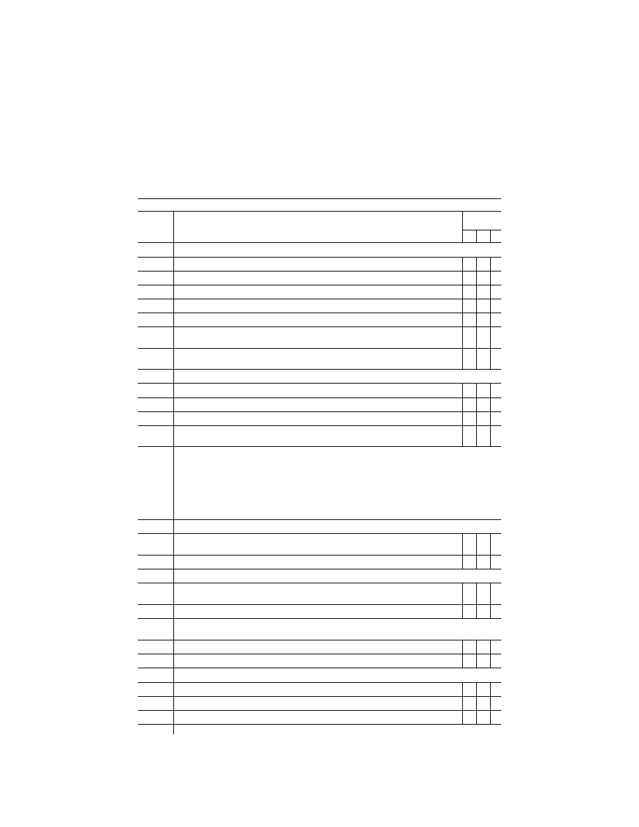
C3C—F
UNCTIONS AND
S
UBJECTIVE
T
ESTS
—Continued
QPS requirements
Entry No.
Visual scene content additional airport or landing area models beyond minimum required for quali-
fication
Class II airport or landing area models
Simulator
level
B C D
2.a. ...........
For Runways:
2.a.1. ........
Strobe lights, approach lights, and edge lights from 5 sm (8 km) of the threshold ...............................
X X X
2.a.2. ........
Centerline lights and taxiway definition from 3 sm (5 km) .....................................................................
X X X
2.a.3. ........
Visual Approach Aid lights (VASI or PAPI) from 3 sm (5 km) of the threshold .....................................
X
2.a.4. ........
Visual Approach Aid lights (VASI or PAPI) from 5 sm (8 km) of the threshold .....................................
X X
2.a.5. ........
Threshold lights and touchdown zone lights from 2 sm (3 km) .............................................................
X X X
2.a.6. ........
Markings within range of landing lights for night/twilight (dusk) scenes and as required by the sur-
face resolution test on daylight scenes.
X X X
2.a.7. ........
For circling approaches, the runway of intended landing and associated lighting must fade into view
in a non-distracting manner.
X X X
2.b. ...........
For Helicopter landing areas:
2.b.1. ........
Landing direction lights and raised FATO lights from 1 sm (1.5 km) ....................................................
X X X
2.b.2. ........
Flush mounted FATO lights, TOFL lights, and the lighted windsock from 0.5 sm (750 m) ..................
X
X
2.b.3. ........
Hover taxiway lighting (yellow/blue/yellow cylinders) from TOFL area ..................................................
X X
2.b.4. ........
Markings within range of landing lights for night/twilight (dusk) scenes and as required by the sur-
face resolution test on daylight scenes.
X X X
3.
..............
Airport or Helicopter landing area model content
The following prescribes the minimum requirements for what must be provided in an airport visual model and iden-
tifies other aspects of the airport environment that must correspond with that model for simulators at Level B, C,
and D. The detail must be developed using airport pictures, construction drawings and maps, or other similar data,
or developed in accordance with published regulatory material; however, this does not require that airport or heli-
copter landing area models contain details that are beyond the designed capability of the currently qualified visual
system. For circling approaches, all requirements of this section apply to the runway used for the initial approach
and to the runway of intended landing. Only one ‘‘primary’’ taxi route from parking to the runway end or helicopter
takeoff/landing area will be required for each ‘‘in-use’’ runway or helicopter takeoff/landing area.
3.a. ...........
The surface and markings for each ‘‘in-use’’ runway or helicopter landing area must include the following:
3.a.1. ........
For airports: Runway threshold markings, runway numbers, touchdown zone markings, fixed dis-
tance markings, runway edge markings, and runway centerline stripes.
X X X
3.a.2. ........
For helicopter landing areas: Standard heliport marking (‘‘H’’), TOFL, FATO, and safety areas ..........
X
X
X
3.b. ...........
The lighting for each ‘‘in-use’’ runway or helicopter landing area must include the following:
3.b.1. ........
For airports: Runway approach, threshold, edge, end, centerline (if applicable), touchdown zone (if
applicable), leadoff, and visual landing aid lights or light systems for that runway.
X X X
3.b.2. ........
For helicopter landing areas: Landing direction, raised and flush FATO, TOFL, windsock lighting ......
X
X
X
3.c. ...........
The taxiway surface and markings associated with each ‘‘in-use’’ runway or helicopter landing area must include
the following:
3.c.1. ........
For airports: Taxiway edge, centerline (if appropriate), runway hold lines, and ILS critical area(s) .....
X
X
X
3.c.2. ........
For helicopter landing areas: Taxiways, taxi routes, and aprons ...........................................................
X X X
3.d. ...........
The taxiway lighting associated with each ‘‘in-use’’ runway or helicopter landing area must include the following:
3.d.1. ........
For airports: Runway edge, centerline (if appropriate), runway hold lines, ILS critical areas ...............
X
X
X
3.d.2. ........
For helicopter landing areas: Taxiways, taxi routes, and aprons ...........................................................
X X X
3.d.3. ........
For airports: Taxiway lighting of correct color ........................................................................................
X
4.
..............
Required visual model correlation with other aspects of the airport environment simulation
VerDate Sep<11>2014
16:30 Jun 25, 2019
Jkt 247047
PO 00000
Frm 00410
Fmt 8010
Sfmt 8002
Q:\14\14V2.TXT
PC31
kpayne on VMOFRWIN702 with $$_JOB