402
14 CFR Ch. I (1–1–19 Edition)
Pt. 60, App. C
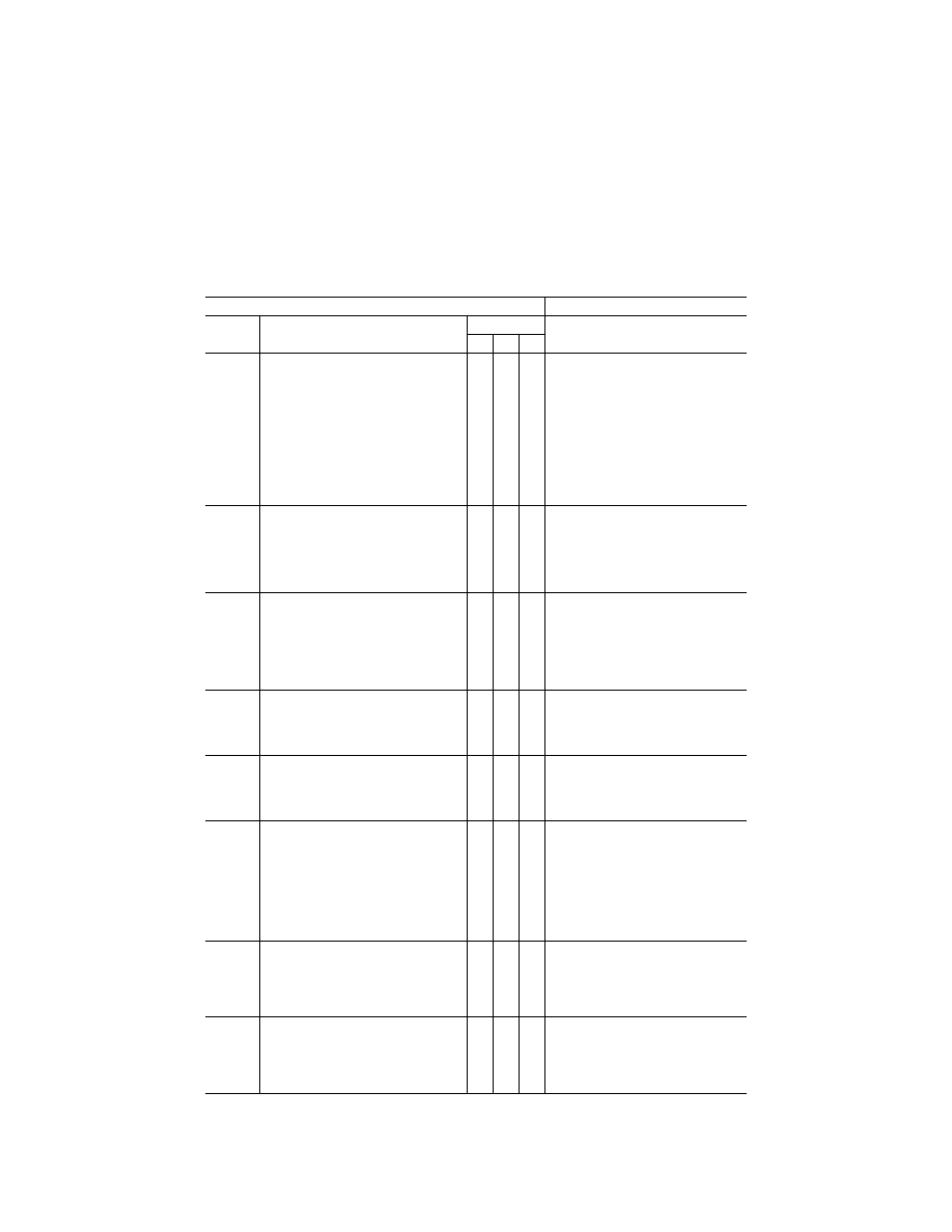
T
ABLE
C3D—F
UNCTIONS AND
S
UBJECTIVE
T
ESTS
—Continued
QPS requirements
Information
Entry No.
Motion system (and special
aerodynamic model) effects
Simulator level
Notes
B C D
1 ...............
Runway rumble, oleo deflection, ground
speed, uneven runway, runway and taxi-
way centerline light characteristics:
Procedure: After the helicopter has been pre-
set to the takeoff position and then released,
taxi at various speeds with a smooth runway
and note the general characteristics of the
simulated runway rumble effects of oleo de-
flections. Repeat the maneuver with a run-
way roughness of 50%, then with maximum
roughness. Note the associated motion vi-
brations affected by ground speed and run-
way roughness
X
X
X If time permits, different gross weights can
also be selected as this may also affect the
associated vibrations depending on heli-
copter type. The associated motion effects
for the above tests should also include an
assessment of the effects of rolling over
centerline lights, surface discontinuities of
uneven runways, and various taxiway char-
acteristics.
2 ...............
Friction Drag from Skid-type Landing Gear:
Procedure: Perform a running takeoff or a run-
ning landing and note an increase in a fuse-
lage vibration (as opposed to rotor vibration)
due to the friction of dragging the skid along
the surface. This vibration will lessen as the
ground speed decreases
X X
3. ..............
Rotor Out-of-Track and/or Out-of-Balance
condition:
Procedure: Select the malfunction or condition
from the IOS. Start the engine(s) normally
and check for an abnormal vibration for an
Out-of-Track condition and check for an ab-
normal vibration for an Out-of-Balance con-
dition
X
X
X
Does not require becoming airborne. The ab-
normal vibration for Out-of-Track and Out-of-
Balance conditions should be recognized in
the frequency range of the inverse of the
period for each; i.e., 1/P for vertical vibra-
tion, and 1/P for lateral vibration.
4. ..............
Bumps associated with the landing gear:
Procedure: Perform a normal take-off paying
special attention to the bumps that could be
perceptible due to maximum oleo extension
after lift-off
X
X
X When the landing gear is extended or re-
tracted, motion bumps can be felt when the
gear locks into position.
5. ..............
Buffet during extension and retraction of
landing gear:
Procedure: Operate the landing gear. Check
that the motion cues of the buffet experi-
enced represent the actual helicopter
X X X
6. ..............
Failure of Dynamic Vibration Absorber or
similar system as appropriate for the hel-
icopter (e.g., droop stop or static stop):
Procedure: May be accomplished any time the
rotor is engaged. Select the appropriate fail-
ure at the IOS, note an appropriate increase
in vibration and check that the vibration in-
tensity and frequency increases with an in-
crease in RPM and an increase in collective
application
X X X
7. ..............
Tail Rotor Drive Failure:
Procedure: With the engine(s) running and the
rotor engaged—select the malfunction and
note the immediate increase of medium fre-
quency vibration
X
X
X The tail rotor operates in the medium fre-
quency range, normally estimated by multi-
plying the tail rotor gear box ratio by the
main rotor RPM. The failure can be recog-
nized by an increase in the vibrations in this
frequency range.
8. ..............
Touchdown cues for main and nose gear:
Procedure: Conduct several normal ap-
proaches with various rates of descent.
Check that the motion cues for the touch-
down bumps for each descent rate are rep-
resentative of the actual helicopter
X X X
VerDate Sep<11>2014
16:30 Jun 25, 2019
Jkt 247047
PO 00000
Frm 00412
Fmt 8010
Sfmt 8002
Q:\14\14V2.TXT
PC31
kpayne on VMOFRWIN702 with $$_JOB