528
14 CFR Ch. I (1–1–19 Edition)
Pt. 135, App. F
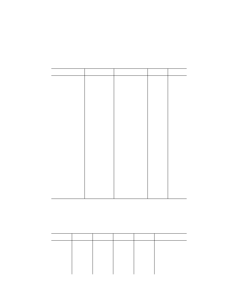
Parameters Range
Accuracy sensor input to
DFDR readout
Sampling inter-
val (per second)
Resolution
2
read out
Altitude ....................................
¥
1,000 ft to max certifi-
cated altitude of air-
craft.
±
100 to
±
700 ft (See Table 1,
TSO-C51a).
1 ........................
5
′
to 30
′
.
Airspeed .................................
As the installed meas-
uring system.
±
3% .......................................
1 ........................
1 kt
Heading ..................................
360
°
................................
±
2
°
.........................................
1 ........................
0.5
°
.
Normal Acceleration (Vertical)
¥
3g to + 6g ...................
±
1% of max range excluding
datum error of
±
5%.
8 ........................
0.01g
Pitch Attitude ..........................
±
75
°
................................
±
2
°
.........................................
2 ........................
0.5
°
Roll Attitude ............................
±
180
°
..............................
±
2
°
.........................................
2 ........................
0.5
°
.
Radio Transmitter Keying .......
On-Off (Discrete) ............
................................................
1 ........................
0.25 sec
Power in Each Engine: Free
Power Turbine Speed
and
Engine Torque.
0–130% (power Turbine
Speed) Full range
(Torque).
±
2% .......................................
1 speed 1
torque (per
engine).
0.2%
1
to 0.4%
1
Main Rotor Speed ..................
0–130% ..........................
±
2% .......................................
2 ........................
0.3%
1
Altitude Rate ...........................
±
6,000 ft/min ...................
As installed ............................
2 ........................
0.2%
1
Pilot Input—Primary Controls
(Collective, Longitudinal Cy-
clic, Lateral Cyclic, Pedal)
3
.
Full range .......................
±
3% .......................................
2 ........................
0.5%
1
Flight Control Hydraulic Pres-
sure Low.
Discrete, each circuit ......
................................................
1 ........................
Flight Control Hydraulic Pres-
sure Selector Switch Posi-
tion, 1st and 2nd stage.
Discrete ..........................
................................................
1 ........................
AFCS Mode and Engagement
Status.
Discrete (5 bits nec-
essary).
................................................
1 ........................
Stability Augmentation System
Engage.
Discrete ..........................
................................................
1 ........................
SAS Fault Status ....................
Discrete ..........................
................................................
0.25 ...................
Main Gearbox Temperature
Low.
As installed .....................
As installed ............................
0.25 ...................
0.5%
1
Main Gearbox Temperature
High.
As installed .....................
As installed ............................
0.5 .....................
0.5%
1
Controllable Stabilator Posi-
tion.
Full Range ......................
±
3% .......................................
2 ........................
0.4%
1
.
Longitudinal Acceleration .......
±
1g ..................................
±
1.5% max range excluding
datum error of
±
5%.
4 ........................
0.01g.
Lateral Acceleration ................
±
1g ..................................
±
1.5% max range excluding
datum of
±
5%.
4 ........................
0.01g.
Master Warning ......................
Discrete ..........................
................................................
1 ........................
Nav 1 and 2 Frequency Se-
lection.
Full range .......................
As installed ............................
0.25 ...................
Outside Air Temperature ........
¥
50
°
C to + 90
°
C .........
±
2
°
c ......................................
0.5 .....................
0.3
°
c
1
Per cent of full range.
2
This column applies to aircraft manufactured after October 11, 1991.
3
For all aircraft manufactured on or after December 6, 2010, the sampling interval per second is 4.
[Doc. No. 25530, 53 FR 26154, July 11, 1988; 53 FR 30906, Aug. 16, 1988; Amdt. 135–113, 73 FR 12571,
Mar. 7, 2008; 73 FR 15281, Mar. 21, 2008; Amdt. 135–121, 75 FR 17047, Apr. 5, 2010]
A
PPENDIX
F
TO
P
ART
135—A
IRPLANE
F
LIGHT
R
ECORDER
S
PECIFICATION
The recorded values must meet the designated range, resolution and accuracy requirements during static and dynamic condi-
tions. Dynamic condition means the parameter is experiencing change at the maximum rate attainable, including the maximum
rate of reversal. All data recorded must be correlated in time to within one second.
Parameters Range
Accuracy (sensor
input)
Seconds per
sampling interval
Resolution Remarks
1. Time or Rel-
ative Time
Counts
1
.
24 Hrs, 0 to
4095.
±
0.125% Per
Hour.
4 ........................
1 sec .................
UTC time preferred when
available. Counter incre-
ments each 4 seconds of
system operation.
2. Pressure Alti-
tude.
¥
1000 ft to max
certificated alti-
tude of aircraft.
+ 5000 ft.
±
100 to
±
700 ft
(see table,
TSO C124a or
TSO C51a).
1 ........................
5
′
to 35
″
.............
Data should be obtained
from the air data computer
when practicable.
3. Indicated air-
speed or Cali-
brated airspeed.
50 KIAS or min-
imum value to
Max V
so
ü
and
V
so
to 1.2 V.
D
.
±
5% and
±
3% ....
1 ........................
1 kt ....................
Data should be obtained
from the air data computer
when practicable.
VerDate Sep<11>2014
08:20 May 17, 2019
Jkt 247048
PO 00000
Frm 00538
Fmt 8010
Sfmt 8002
Y:\SGML\247048.XXX
247048