854
14 CFR Ch. I (1–1–19 Edition)
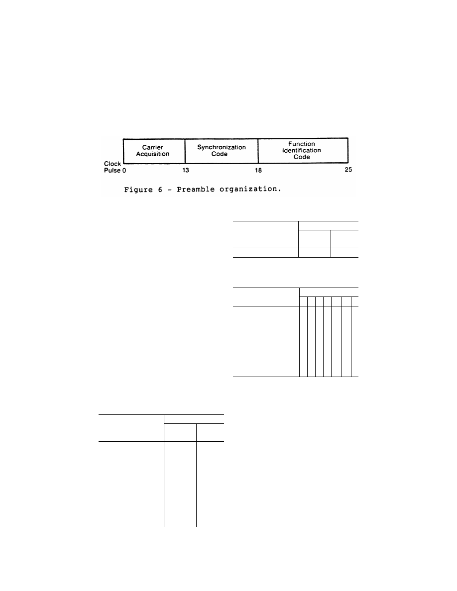
§ 171.311
(i)
Digital codes.
The coding used in
the preamble for receiver synchroni-
zation is a Barker code logic 11101. The
time of the last phase transition mid-
point in the code shall be the receiver
reference time (see Table 2). The func-
tion identification codes must be as
shown in Table 3. The last two bits (I
11
and I
12
) of the code are parity bits
obeying the equations:
I
6
+ I
7
+ I
8
+ I
9
+ I
10
+ I
11
= Even
I
6
+ I
8
+ I
10
+ I
12
= Even
(ii)
Data modulation.
The digital code
portions of the preamble must be
DPSK modulated in accordance with
§ 171.311(c)(1) and must be transmitted
throughout the function coverage vol-
ume.
(2)
Angle function formats.
The timing
of the angle transmissions must be in
accordance with Tables 4a, 4b, and 5.
The actual timing of the TO and FRO
scans must be as required to meet the
accuracy requirements of §§ 171.313 and
171.317.
(i) Preamble. Must be in accordance
with requirements of § 171.311(i)(1).
T
ABLE
2—P
REAMBLE
T
IMING
1
Event
Event time slot begins at—
15.625 kHz
clock pulse
(number)
Time (milli-
seconds)
Carrier acquisition:
(CW transmission) ...............
0
0
Receiver reference time code:
I
1
= 1 ....................................
13
0 .832
I
2
= 1 ....................................
14
0 .896
I
3
= 1 ....................................
15
0 .960
I
4
= 0 ....................................
16
1 .024
I
5
= 1 ....................................
17
2
1 .088
Function identification:
I
6
...........................................
18 1
.152
I
7
...........................................
19 1
.216
I
8
...........................................
20 1
.280
I
9
...........................................
21 1
.344
I
10
(see table 1) ....................
22
1 .408
I
11
.........................................
23 1
.472
I
12
.........................................
24 1
.536
T
ABLE
2—P
REAMBLE
T
IMING
1
—Continued
Event
Event time slot begins at—
15.625 kHz
clock pulse
(number)
Time (milli-
seconds)
END PREAMBLE .................
25
1 .600
1
Applies to all functions transmitted.
2
Reference time for receiver synchronization for all function
timing.
T
ABLE
3—F
UNCTION
I
DENTIFICATION
C
ODES
Function
Code
I
6
I
7
I
8
I
9
I
10
I
11
I
12
Approach
azimuth ....................
0 0 1 1 0 0 1
High rate approach azimuth .....
0 0 1 0
1
0
0
Approach
elevation ..................
1 1 0 0 0 0 1
Back
azimuth ............................
1 0 0 1 0 0 1
Basic
data
1 .............................
0 1 0 1 0 0 0
Basic
data
2 .............................
0 1 1 1 1 0 0
Basic
data
3 .............................
1 0 1 0 0 0 0
Basic
data
4 .............................
1 0 0 0 1 0 0
Basic
data
5 .............................
1 1 0 1 1 0 0
Dasic
data
6 .............................
0 0 0 1 1 0 1
Auxiliary data A ........................
1 1 1 0
0
1
0
Auxiliary data B ........................
1 0 1 0
1
1
1
Auxiliary data C ........................
1 1 1 1
0
0
0
(ii)
Sector signals.
In all azimuth for-
mats, sector signals must be trans-
mitted to provide Morse Code identi-
fication, airborne antenna selection,
and system test signals. These signals
are not required in the elevation for-
mats. In addition, if the signal from an
installed ground component results in
a valid indication in an area where no
valid guidance should exist, OCI signals
must be radiated as provided for in the
signal format (see Tables 4a, 4b, and 5).
The sector signals are defined as fol-
lows:
(A)
Morse Code.
DPSK transmissions
that will permit Morse Code facility
identification in the aircraft by a four
letter code starting with the letter
‘‘M’’ must be included in all azimuth
functions. They must be transmitted
and repeated at approximately equal
intervals, not less than six times per
VerDate Sep<11>2014
08:20 May 17, 2019
Jkt 247048
PO 00000
Frm 00864
Fmt 8010
Sfmt 8010
Y:\SGML\247048.XXX
247048
EC15SE91.010</GPH>