857
Federal Aviation Administration, DOT
§ 171.311
(B)
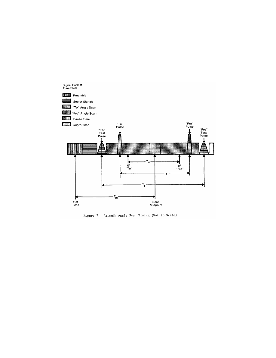
Azimuth angle encoding.
Each
guidance angle transmitted must con-
sist of a clockwise TO scan followed by
a counterclockwise FRO scan as viewed
from above the antenna. For approach
azimuth functions, increasing angle
values must be in the direction of the
TO scan; for the back azimuth func-
tion, increasing angle values must be
in the direction of the FRO scan. The
antenna has a narrow beam in the
plane of the scan direction and a broad
beam in the orthogonal plane which
fills the vertical coverage.
(C)
Elevation angle encoding.
The radi-
ation from elevation equipment must
produce a beam which scans from the
horizon up to the highest elevation
angle and then scans back down to the
horizon. The antenna has a narrow
beam in the plane of the scan direction
and a broad beam in the orthogonal
plane which fills the horizontal cov-
erage. Elevation angles are defined
from the horizontal plane containing
the antenna phase center; positive an-
gles are above the horizontal and zero
angle is along the horizontal.
(iv)
Clearance guidance.
The timing of
the clearance pulses must be in accord-
ance with Figure 8. For azimuth ele-
ments with proportional coverage of
less than
±
40 degrees (
±
20 degrees for
back azimuth), clearance guidance in-
formation must be provided by trans-
mitting pulses in a TO and FRO format
adjacent to the stop/start times of the
scanning beam signal. The fly-right
clearance pulses must represent posi-
tive angles and the fly-left clearance
pulses must represent negative angles.
The duration of each clearance pulse
must be 50 microseconds with a toler-
ance of
±
5 microseconds. The trans-
mitter switching time between the
clearance pulses and the scanning
VerDate Sep<11>2014
08:20 May 17, 2019
Jkt 247048
PO 00000
Frm 00867
Fmt 8010
Sfmt 8010
Y:\SGML\247048.XXX
247048
EC15SE91.012</GPH>