868
14 CFR Ch. I (1–1–19 Edition)
§ 171.313
the coverage requirement is reduced to
14 nm beyond
±
40
°
.
(2) Vertically between:
(i) A conical surface originating 2.5
meters (8 feet) above the runway cen-
terline at threshold inclined at 0.9 de-
gree above the horizontal.
(ii) A conical surface originating at
the azimuth ground equipment antenna
inclined at 15 degrees above the hori-
zontal to a height of 6,000 meters (20,000
feet).
(iii) Where intervening obstacles pen-
etrate the lower surface, coverage need
be provided only to the minimum line
of sight.
(3) Runway region:
(i) Proportional guidance hori-
zontally within a sector 45 meters (150
feet) each side of the runway centerline
beginning at the stop end and extend-
ing parallel with the runway centerline
in the direction of the approach to join
the approach region. This requirement
does not apply to offset azimuth instal-
lations.
(ii) Vertically between a horizontal
surface which is 2.5 meters (8 feet)
above the farthest point of runway cen-
terline which is in line of sight of the
azimuth antenna, and in a conical sur-
face originating at the azimuth ground
equipment antenna inclined at 20 de-
grees above the horizontal up to a
height to 600 meters (2,000 feet). This
requirement does not apply to offset
azimuth installations.
(4) Within the approach azimuth cov-
erage sector defined in paragraphs (a)
(1), and (2) and (3) of this section, the
power densities must not be less than
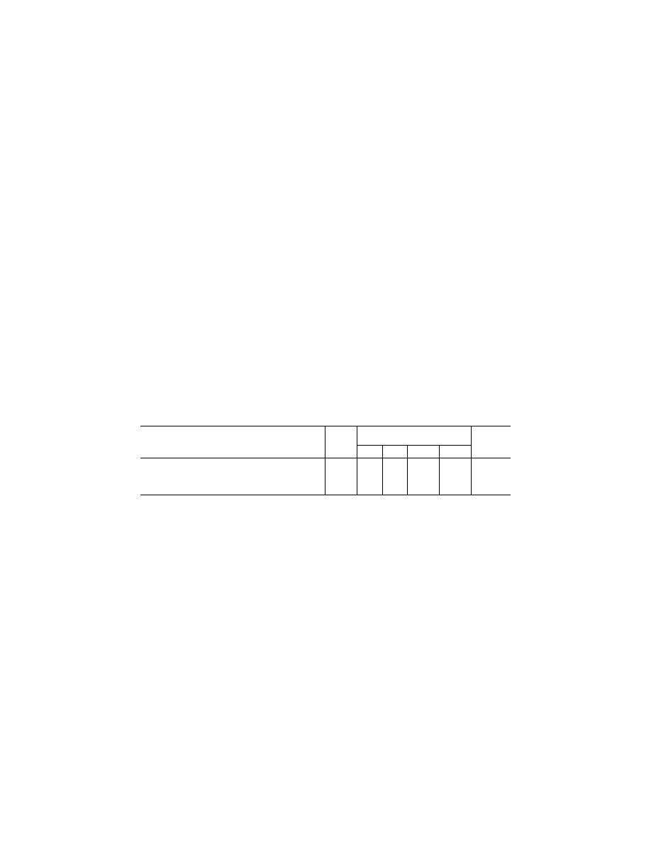
those shown in Table 9 but the equip-
ment design must also allow for:
(i) Transmitter power degradation
from normal by
¥
1.5 dB;
T
ABLE
9—M
INIMUM
P
OWER
D
ENSITY
W
ITHIN
C
OVERAGE
B
OUNDARIES
(
D
BW/
M
2
)
Function
Data
signals
Angle signals for various antenna
beamwidths Clearance
signals
1
°
1.5
°
2
°
3
°
Approach azimuth .......................................................................
¥
89.5
¥
88 ..........
¥
85.5
¥
82
¥
88
High rate approach azimuth ........................................................
¥
89.5
¥
88 ..........
¥
88
¥
86.5
¥
88
Back azimuth ...............................................................................
¥
89.5
¥
88 ..........
¥
85.5
¥
82
¥
88
Approach elevation .....................................................................
¥
89.5
¥
88
¥
88
¥
88 ..............
....................
(ii) Rain loss of
¥
2.2 dB at the longi-
tudinal coverage extremes.
(b)
Siting requirements.
The approach
azimuth antenna system must, except
as allowed in paragraph (c) of this sec-
tion:
(1) Be located on the extension of the
centerline of the runway beyond the
stop end;
(2) Be adjusted so that the zero de-
gree azimuth plane will be a vertical
plane which contains the centerline of
the runway served;
(3) Have the minimum height nec-
essary to comply with the coverage re-
quirements prescribed in paragraph (a)
of this section;
(4) Be located at a distance from the
stop end of the runway that is con-
sistent with safe obstruction clearance
practices;
(5) Not obscure any light of an ap-
proach lighting system; and
(6) Be installed on frangible mounts
or beyond the 300 meter (1,000 feet)
light bar.
(c) On runways where limited terrain
prevents the azimuth antenna from
being positioned on the runway center-
line extended, and the cost of the land
fill or a tall tower antenna support is
prohibitive, the azimuth antenna may
be offset.
(d)
Antenna coordinates.
The scanning
beams transmitted by the approach
azimuth equipment within
±
40
°
of the
centerline may be either conical or
planar.
(e)
Approach azimuth accuracy.
(1) The
system and subsystem errors shall not
exceed those listed in Table 10 at the
approach reference datum.
At the approach reference datum,
temporal sinusoidal noise components
shall not exceed 0.025 degree peak in
the frequency band 0.01 Hz to 1.6 Hz,
and the CMN shall not exceed 0.10 de-
gree. From the approach reference
VerDate Sep<11>2014
08:20 May 17, 2019
Jkt 247048
PO 00000
Frm 00878
Fmt 8010
Sfmt 8010
Y:\SGML\247048.XXX
247048