877
Federal Aviation Administration, DOT
§ 171.317
(4) Within the elevation coverage sec-
tor defined in paragraphs (a) (1), (2) and
(3) of this section, the power densities
must not be less than those shown in
Table 9, but the equipment design must
also allow for:
(i) Transmitter power degradation
from normal by
¥
1.5 dB.
(ii) Rain loss of
¥
2.2 dB at the cov-
erage extremes.
(b)
Elevation siting requirements.
The
Elevation Antenna System must:
(1) Be located as close to runway cen-
terline as possible (without violating
obstacle clearance criteria).
(2) Be located near runway threshold
such that the asymptote of the min-
imum glidepath crosses the threshold
of the runway at the Approach Ref-
erence Datum height. Normally, the
minimum glidepath should be 3 degrees
and the Approach Reference Datum
height should be 50 feet. However,
there are circumstances where other
glideslopes and reference datum
heights are appropriate. Some of these
instances are discussed in FAA Order
8260.34 (Glide Slope Threshold Crossing
Height Requirements) and Order 8260.3
(IFR Approval of MLS.)
(3) Be located such that the MLS Ap-
proach Reference Datum and ILS Ref-
erence Datum heights are coincident
within a tolerance of 3 feet when MLS
is installed on a runway already served
by an ILS. This requirement applies
only if the ILS glide slope is sited such
that the height of the reference datum
meets the requirements of FAA Order
8260.34.
(c)
Antenna coordinates.
The scanning
beams transmitted by the elevation
subsystem must be conical.
(d)
Elevation accuracy.
(1) The accura-
cies shown in Table 13 are required at
the approach reference datum. From
the approach reference datum to the
coverage limit, the PFE, PFN and CMN
limits shall be allowed to linearly in-
crease as follows:
(i) With distance along the runway
centerline extended at the minimum
glide path angle, by a factor of 1.2 for
the PFE and PFN limits and to
±
0.10
degree for the CMN limits;
(ii) With azimuth angle, from runway
centerline extended to the coverage ex-
treme, by a factor of 1.2 for the PFE
and PFN limits and by a factor of 2.0
for the CMN limits;
(iii) With increasing elevation angles
from + 3 degrees to + 15 degrees, by a
factor of 2.0 for the PFE and PFN lim-
its;
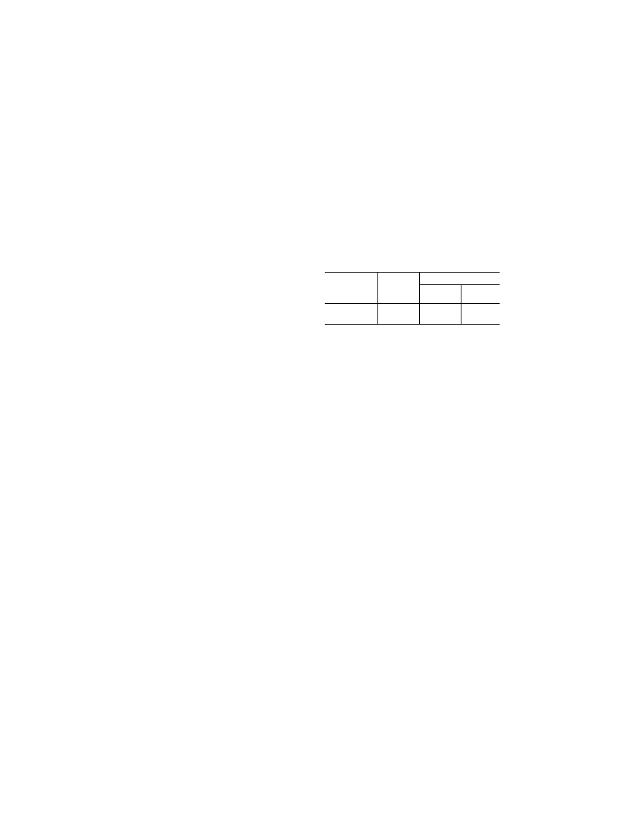
T
ABLE
13—E
LEVATION
A
CCURACIES AT THE
A
PPROACH
R
EFERENCE
D
ATUM
Error type
System
Angular error (degrees)
Ground sub-
system
Airborne
subsystem
4
PFE ....................
1 2
±
0.133 (
3
)
±
0.017
CMN ..................
1
±
0.050
±
0.020
±
0.010
Notes:
1
Includes errors due to ground and airborne equipment and
propagation effects.
2
The system PFN component must not exceed
±
0.087 de-
gree.
3
The mean (bias) error component contributed by the
ground equipment should not exceed
±
0.067 degree.
4
The airborne subsystem angular errors are provided for in-
formation only.
(iv) With decreasing elevation angle
from + 3 degrees (or 60% of the min-
imum glide path angle, whichever is
less) to the coverage extreme, by a fac-
tor of 3 for the PFE, PFN and CMN
limits; and
(v) Maximum angular limits. the
CMN limits shall not exceed
±
0.10 de-
gree in any coverage region within
±
10
degrees laterally of runway centerline
extended which is above the elevation
angle specified in (iv) above.
N
OTE
: It is desirable that the CMN not ex-
ceed
±
0.10 degree throughout the coverage re-
gion above the elevation angle specified in
paragraph (d)(1)(iv) of this section.
(2) The system and ground subsystem
accuracies shown in Table 13 are to be
demonstrated at commissioning as
maximum error limits. Subsequent to
commissioning, the accuracies are to
be considered at 95% probability limits.
(e) Elevation antenna characteristics
are as follows:
(1)
Drift.
Any elevation angle as en-
coded by the scanning beam at any
point within the coverage sector must
not vary more than 0.04 degree over the
range of service conditions specified in
§ 171.309(d) without the use of internal
environmental controls. Multipath ef-
fects are excluded from this require-
ment.
(2)
Beam pointing errors.
The elevation
angle as encoded by the scanning beam
at any point within the coverage sector
VerDate Sep<11>2014
08:20 May 17, 2019
Jkt 247048
PO 00000
Frm 00887
Fmt 8010
Sfmt 8010
Y:\SGML\247048.XXX
247048