218
14 CFR Ch. I (1–1–14 Edition)
§ 23.399
2
If the design of any individual set of control systems or
surfaces makes these specified minimum forces or torques in-
applicable, values corresponding to the present hinge mo-
ments obtained under § 23.415, but not less than 0.6 of the
specified minimum forces or torques, may be used.
3
The critical parts of the aileron control system must also
be designed for a single tangential force with a limit value of
1.25 times the couple force determined from the above cri-
teria.
4
D=wheel diameter (inches).
5
The unsymmetrical force must be applied at one of the
normal handgrip points on the control wheel.
[Doc. No. 4080, 29 FR 17955, Dec. 18, 1964, as
amended by Amdt. 23–7, 34 FR 13089, Aug. 13,
1969; Amdt. 23–17, 41 FR 55464, Dec. 20, 1976;
Amdt. 23–34, 52 FR 1829, Jan. 15, 1987; Amdt.
23–45, 58 FR 42160, Aug. 6, 1993]
§ 23.399
Dual control system.
(a) Each dual control system must be
designed to withstand the force of the
pilots operating in opposition, using in-
dividual pilot forces not less than the
greater of—
(1) 0.75 times those obtained under
§ 23.395; or
(2) The minimum forces specified in
§ 23.397(b).
(b) Each dual control system must be
designed to withstand the force of the
pilots applied together, in the same di-
rection, using individual pilot forces
not less than 0.75 times those obtained
under § 23.395.
[Doc. No. 27805, 61 FR 5145, Feb. 9, 1996]
§ 23.405
Secondary control system.
Secondary controls, such as wheel
brakes, spoilers, and tab controls, must
be designed for the maximum forces
that a pilot is likely to apply to those
controls.
§ 23.407
Trim tab effects.
The effects of trim tabs on the con-
trol surface design conditions must be
accounted for only where the surface
loads are limited by maximum pilot ef-
fort. In these cases, the tabs are con-
sidered to be deflected in the direction
that would assist the pilot. These de-
flections must correspond to the max-
imum degree of ‘‘out of trim’’ expected
at the speed for the condition under
consideration.
§ 23.409
Tabs.
Control surface tabs must be de-
signed for the most severe combination
of airspeed and tab deflection likely to
be obtained within the flight envelope
for any usable loading condition.
§ 23.415
Ground gust conditions.
(a) The control system must be inves-
tigated as follows for control surface
loads due to ground gusts and taxiing
downwind:
(1) If an investigation of the control
system for ground gust loads is not re-
quired by paragraph (a)(2) of this sec-
tion, but the applicant elects to design
a part of the control system of these
loads, these loads need only be carried
from control surface horns through the
nearest stops or gust locks and their
supporting structures.
(2) If pilot forces less than the mini-
mums specified in § 23.397(b) are used
for design, the effects of surface loads
due to ground gusts and taxiing down-
wind must be investigated for the en-
tire control system according to the
formula:
H=K c S q
where—
H=limit hinge moment (ft.-lbs.);
c=mean chord of the control surface aft of
the hinge line (ft.);
S=area of control surface aft of the hinge
line (sq. ft.);
q=dynamic pressure (p.s.f.) based on a design
speed not less than 14.6
√
(W/S) + 14.6
(f.p.s.) where W/S=wing loading at design
maximum weight, except that the design
speed need not exceed 88 (f.p.s.);
K=limit hinge moment factor for ground
gusts derived in paragraph (b) of this sec-
tion. (For ailerons and elevators, a posi-
tive value of K indicates a moment tend-
ing to depress the surface and a negative
value of K indicates a moment tending to
raise the surface).
(b) The limit hinge moment factor
K
for ground gusts must be derived as fol-
lows:
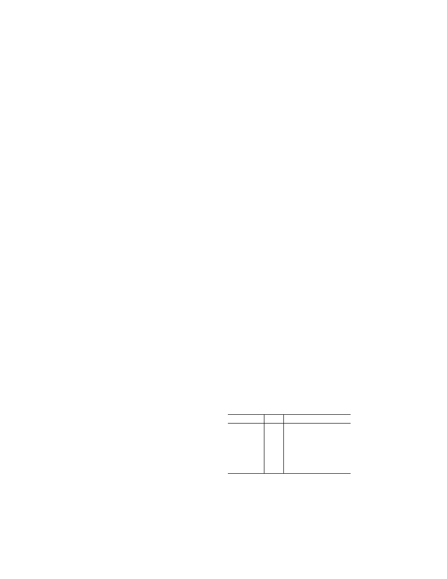
Surface
K
Position of controls
(a) Aileron .........
0.75 Control column locked lashed in
mid-position.
(b) Aileron .........
±
0.50 Ailerons at full throw; + moment
on one aileron,
¥
moment on
the other.
(c) Elevator .......
±
0.75 (c) Elevator full up (
¥
).
(d) Elevator .......
............
(d) Elevator full down (+).
(e) Rudder .........
±
0.75 (e) Rudder in neutral.
(f) Rudder ..........
............
(f) Rudder at full throw.
(c) At all weights between the empty
weight and the maximum weight de-
clared for tie-down stated in the appro-
priate manual, any declared tie-down
points and surrounding structure, con-
trol system, surfaces and associated
VerDate Mar<15>2010
10:12 Mar 18, 2014
Jkt 232046
PO 00000
Frm 00228
Fmt 8010
Sfmt 8010
Y:\SGML\232046.XXX
232046
pmangrum on DSK3VPTVN1PROD with CFR