220
14 CFR Ch. I (1–1–14 Edition)
§ 23.427
S
ht
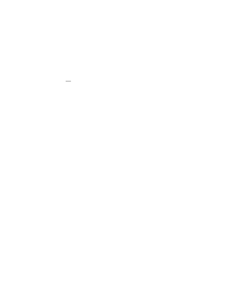
=Area of aft horizontal lift surface (ft
2
);
and
1
−
⎛
⎝⎜
⎞
⎠⎟
=
d
d
ε
α
Downwash factor
[Doc. No. 4080, 29 FR 17955, Dec. 18, 1964, as
amended by Amdt. 23–7, 34 FR 13089 Aug. 13,
1969; Amdt. 23–42, 56 FR 353, Jan. 3, 1991]
§ 23.427
Unsymmetrical loads.
(a) Horizontal surfaces other than
main wing and their supporting struc-
ture must be designed for unsymmet-
rical loads arising from yawing and
slipstream effects, in combination with
the loads prescribed for the flight con-
ditions set forth in §§ 23.421 through
23.425.
(b) In the absence of more rational
data for airplanes that are conven-
tional in regard to location of engines,
wings, horizontal surfaces other than
main wing, and fuselage shape:
(1) 100 percent of the maximum load-
ing from the symmetrical flight condi-
tions may be assumed on the surface
on one side of the plane of symmetry;
and
(2) The following percentage of that
loading must be applied to the opposite
side:
Percent=100¥10 (n¥1), where n is the spec-
ified positive maneuvering load factor, but
this value may not be more than 80 percent.
(c) For airplanes that are not conven-
tional (such as airplanes with hori-
zontal surfaces other than main wing
having appreciable dihedral or sup-
ported by the vertical tail surfaces) the
surfaces and supporting structures
must be designed for combined vertical
and horizontal surface loads resulting
from each prescribed flight condition
taken separately.
[Amdt. 23–14, 38 FR 31820, Nov. 19, 1973, as
amended by Amdt. 23–42, 56 FR 353, Jan. 3,
1991]
V
ERTICAL
S
URFACES
§ 23.441
Maneuvering loads.
(a) At speeds up to
V
A,
the vertical
surfaces must be designed to withstand
the following conditions. In computing
the loads, the yawing velocity may be
assumed to be zero:
(1) With the airplane in unacceler-
ated flight at zero yaw, it is assumed
that the rudder control is suddenly dis-
placed to the maximum deflection, as
limited by the control stops or by limit
pilot forces.
(2) With the rudder deflected as speci-
fied in paragraph (a)(1) of this section,
it is assumed that the airplane yaws to
the overswing sideslip angle. In lieu of
a rational analysis, an overswing angle
equal to 1.5 times the static sideslip
angle of paragraph (a)(3) of this section
may be assumed.
(3) A yaw angle of 15 degrees with the
rudder control maintained in the neu-
tral position (except as limited by pilot
strength).
(b) For commuter category airplanes,
the loads imposed by the following ad-
ditional maneuver must be substan-
tiated at speeds from V
A
to V
D
/M
D
.
When computing the tail loads—
(1) The airplane must be yawed to the
largest attainable steady state sideslip
angle, with the rudder at maximum de-
flection caused by any one of the fol-
lowing:
(i) Control surface stops;
(ii) Maximum available booster ef-
fort;
(iii) Maximum pilot rudder force as
shown below:
VerDate Mar<15>2010
10:12 Mar 18, 2014
Jkt 232046
PO 00000
Frm 00230
Fmt 8010
Sfmt 8010
Y:\SGML\232046.XXX
232046
EC28SE91.003</MATH>
pmangrum on DSK3VPTVN1PROD with CFR