233
Federal Aviation Administration, DOT
§ 23.571
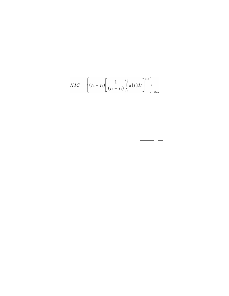
(ii) The value of HIC is defined as—
Where—
t
1
is the initial integration time, expressed
in seconds, t
2
is the final integration
time, expressed in seconds, and a(t) is the
total acceleration vs. time curve for the
head strike expressed as a multiple of g
(units of gravity).
(iii) Compliance with the HIC limit
must be demonstrated by measuring
the head impact during dynamic test-
ing as prescribed in paragraphs (b)(1)
and (b)(2) of this section or by a sepa-
rate showing of compliance with the
head injury criteria using test or anal-
ysis procedures.
(6) Loads in individual shoulder har-
ness straps may not exceed 1,750
pounds. If dual straps are used for re-
taining the upper torso, the total strap
loads may not exceed 2,000 pounds.
(7) The compression load measured
between the pelvis and the lumbar
spine of the ATD may not exceed 1,500
pounds.
(d) For all single-engine airplanes
with a V
SO
of more than 61 knots at
maximum weight, and those multien-
gine airplanes of 6,000 pounds or less
maximum weight with a V
SO
of more
than 61 knots at maximum weight that
do not comply with § 23.67(a)(1);
(1) The ultimate load factors of
§ 23.561(b) must be increased by multi-
plying the load factors by the square of
the ratio of the increased stall speed to
61 knots. The increased ultimate load
factors need not exceed the values
reached at a V
S0
of 79 knots. The up-
ward ultimate load factor for acrobatic
category airplanes need not exceed
5.0g.
(2) The seat/restraint system test re-
quired by paragraph (b)(1) of this sec-
tion must be conducted in accordance
with the following criteria:
(i) The change in velocity may not be
less than 31 feet per second.
(ii)(A) The peak deceleration (g
p
) of
19g and 15g must be increased and mul-
tiplied by the square of the ratio of the
increased stall speed to 61 knots:
g
p
=19.0 (V
S0
/61)
2
or g
p
=15.0 (V
S0
/61)
2
(B) The peak deceleration need not
exceed the value reached at a V
S0
of 79
knots.
(iii) The peak deceleration must
occur in not more than time (t
r
), which
must be computed as follows:
t
31
32.2 g
.96
g
r
p
p
=
( )
=
where—
g
p
=The peak deceleration calculated in ac-
cordance with paragraph (d)(2)(ii) of this
section
t
r
=The rise time (in seconds) to the peak de-
celeration.
(e) An alternate approach that
achieves an equivalent, or greater,
level of occupant protection to that re-
quired by this section may be used if
substantiated on a rational basis.
[Amdt. 23–36, 53 FR 30812, Aug. 15, 1988, as
amended by Amdt. 23–44, 58 FR 38639, July 19,
1993; Amdt. 23–50, 61 FR 5192, Feb. 9, 1996;
Amdt. 23–62, 76 FR 75756, Dec. 2, 2011]
F
ATIGUE
E
VALUATION
§ 23.571
Metallic pressurized cabin
structures.
For normal, utility, and acrobatic
category airplanes, the strength, detail
design, and fabrication of the metallic
structure of the pressure cabin must be
evaluated under one of the following:
(a) A fatigue strength investigation
in which the structure is shown by
tests, or by analysis supported by test
evidence, to be able to withstand the
repeated loads of variable magnitude
expected in service; or
(b) A fail safe strength investigation,
in which it is shown by analysis, tests,
or both that catastrophic failure of the
structure is not probable after fatigue
VerDate Mar<15>2010
10:12 Mar 18, 2014
Jkt 232046
PO 00000
Frm 00243
Fmt 8010
Sfmt 8010
Y:\SGML\232046.XXX
232046
ER02DE11.083</GPH>
EC28SE91.013</MATH>
pmangrum on DSK3VPTVN1PROD with CFR