346
14 CFR Ch. I (1–1–14 Edition)
Pt. 23, App. F
(h)
Burn length. Burn length is the distance
from the original edge to the farthest evi-
dence of damage to the test specimen due to
flame impingement, including areas of par-
tial or complete consumption, charring, or
embrittlement, but not including areas soot-
ed, stained, warped, or discolored, nor areas
where material has shrunk or melted away
from the heat source.
P
ART
II—T
EST
M
ETHOD
T
O
D
ETERMINE THE
F
LAMMABILITY
AND
F
LAME
P
ROPAGATION
C
HARACTERISTICS OF
T
HERMAL
/A
COUSTIC
I
N
-
SULATION
M
ATERIALS
Use this test method to evaluate the flam-
mability and flame propagation characteris-
tics of thermal/acoustic insulation when ex-
posed to both a radiant heat source and a
flame.
(a)
Definitions.
Flame propagation means the furthest dis-
tance of the propagation of visible flame to-
wards the far end of the test specimen, meas-
ured from the midpoint of the ignition
source flame. Measure this distance after
initially applying the ignition source and be-
fore all flame on the test specimen is extin-
guished. The measurement is not a deter-
mination of burn length made after the test.
Radiant heat source means an electric or air
propane panel.
Thermal/acoustic insulation means a mate-
rial or system of materials used to provide
thermal and/or acoustic protection. Exam-
ples include fiberglass or other batting mate-
rial encapsulated by a film covering and
foams.
Zero point means the point of application of
the pilot burner to the test specimen.
(b)
Test apparatus.
(1)
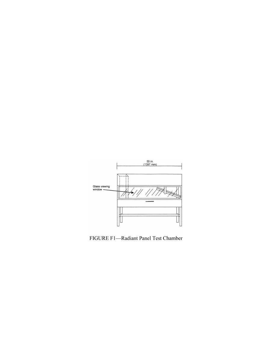
Radiant panel test chamber. Conduct
tests in a radiant panel test chamber (see
figure F1 above). Place the test chamber
under an exhaust hood to facilitate clearing
the chamber of smoke after each test. The
radiant panel test chamber must be an enclo-
sure 55 inches (1397 mm) long by 19.5 inches
(495 mm) deep by 28 inches (710 mm) to 30
inches (maximum) (762 mm) above the test
specimen. Insulate the sides, ends, and top
with a fibrous ceramic insulation, such as
Kaowool MTM board. On the front side, pro-
vide a 52 by 12-inch (1321 by 305 mm) draft-
free, high-temperature, glass window for
viewing the sample during testing. Place a
door below the window to provide access to
the movable specimen platform holder. The
bottom of the test chamber must be a sliding
steel platform that has provision for secur-
ing the test specimen holder in a fixed and
level position. The chamber must have an in-
ternal chimney with exterior dimensions of
5.1 inches (129 mm) wide, by 16.2 inches (411
mm) deep by 13 inches (330 mm) high at the
opposite end of the chamber from the radiant
energy source. The interior dimensions must
be 4.5 inches (114 mm) wide by 15.6 inches (395
mm) deep. The chimney must extend to the
top of the chamber (see figure F2).
VerDate Mar<15>2010
10:12 Mar 18, 2014
Jkt 232046
PO 00000
Frm 00356
Fmt 8010
Sfmt 8002
Y:\SGML\232046.XXX
232046
ER02DE11.087</GPH>
pmangrum on DSK3VPTVN1PROD with CFR