360
14 CFR Ch. I (1–1–14 Edition)
Pt. 25
T
ABLE
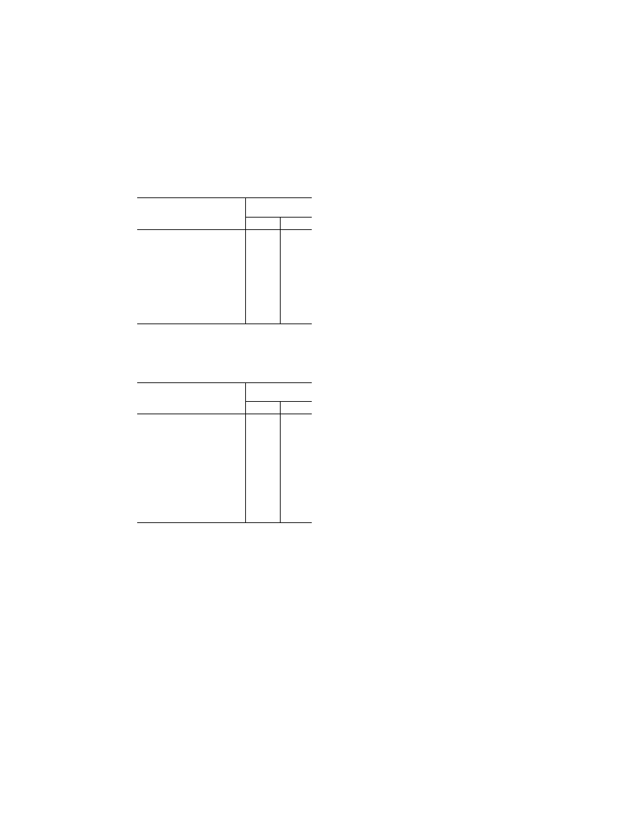
I.—HIRF E
NVIRONMENT
I
Frequency
Field strength
(volts/meter)
Peak Average
10 kHz–2 MHz ...................................
50
50
2 MHz–30 MHz .................................
100
100
30 MHz–100 MHz .............................
50
50
100 MHz–400 MHz ...........................
100
100
400 MHz–700 MHz ...........................
700
50
700 MHz–1 GHz ................................
700
100
GHz–2 GHz .......................................
2,000
200
2 GHz–6 GHz ....................................
3,000
200
6 GHz–8 GHz ....................................
1,000
200
8 GHz–12 GHz ..................................
3,000
300
12 GHz–18 GHz ................................
2,000
200
18 GHz–40 GHz ................................
600
200
In this table, the higher field strength applies at the fre-
quency band edges.
(b) HIRF environment II is specified in the
following table:
T
ABLE
II.–HIRF E
NVIRONMENT
II
Frequency
Field strength
(volts/meter)
Peak Average
10 kHz–500 kHz ................................
20
20
500 kHz–2 MHz .................................
30
30
2 MHz–30 MHz .................................
100
100
30 MHz–100 MHz .............................
10
10
100 MHz–200 MHz ...........................
30
10
200 MHz–400 MHz ...........................
10
10
400 MHz–1 GHz ................................
700
40
1 GHz–2 GHz ....................................
1,300
160
2 GHz–4 GHz ....................................
3,000
120
4 GHz–6 GHz ....................................
3,000
160
6 GHz–8 GHz ....................................
400
170
8 GHz–12 GHz ..................................
1,230
230
12 GHz–18 GHz ................................
730
190
18 GHz–40 GHz ................................
600
150
In this table, the higher field strength applies at the fre-
quency band edges.
(c)
Equipment HIRF Test Level 1. (1) From 10
kilohertz (kHz) to 400 megahertz (MHz), use
conducted susceptibility tests with contin-
uous wave (CW) and 1 kHz square wave mod-
ulation with 90 percent depth or greater. The
conducted susceptibility current must start
at a minimum of 0.6 milliamperes (mA) at 10
kHz, increasing 20 decibels (dB) per fre-
quency decade to a minimum of 30 mA at 500
kHz.
(2) From 500 kHz to 40 MHz, the conducted
susceptibility current must be at least 30
mA.
(3) From 40 MHz to 400 MHz, use conducted
susceptibility tests, starting at a minimum
of 30 mA at 40 MHz, decreasing 20 dB per fre-
quency decade to a minimum of 3 mA at 400
MHz.
(4) From 100 MHz to 400 MHz, use radiated
susceptibility tests at a minimum of 20 volts
per meter (V/m) peak with CW and 1 kHz
square wave modulation with 90 percent
depth or greater.
(5) From 400 MHz to 8 gigahertz (GHz), use
radiated susceptibility tests at a minimum
of 150 V/m peak with pulse modulation of 4
percent duty cycle with a 1 kHz pulse repeti-
tion frequency. This signal must be switched
on and off at a rate of 1 Hz with a duty cycle
of 50 percent.
(d)
Equipment HIRF Test Level 2. Equipment
HIRF test level 2 is HIRF environment II in
table II of this appendix reduced by accept-
able aircraft transfer function and attenu-
ation curves. Testing must cover the fre-
quency band of 10 kHz to 8 GHz.
(e)
Equipment HIRF Test Level 3. (1) From 10
kHz to 400 MHz, use conducted susceptibility
tests, starting at a minimum of 0.15 mA at 10
kHz, increasing 20 dB per frequency decade
to a minimum of 7.5 mA at 500 kHz.
(2) From 500 kHz to 40 MHz, use conducted
susceptibility tests at a minimum of 7.5 mA.
(3) From 40 MHz to 400 MHz, use conducted
susceptibility tests, starting at a minimum
of 7.5 mA at 40 MHz, decreasing 20 dB per fre-
quency decade to a minimum of 0.75 mA at
400 MHz.
(4) From 100 MHz to 8 GHz, use radiated
susceptibility tests at a minimum of 5 V/m.
[Doc. No. FAA–2006–23657, 72 FR 44025, Aug. 6,
2007]
PART 25—AIRWORTHINESS STAND-
ARDS: TRANSPORT CATEGORY
AIRPLANES
S
PECIAL
F
EDERAL
A
VIATION
R
EGULATION
N
O
.
13
S
PECIAL
F
EDERAL
A
VIATION
R
EGULATION
N
O
.
109
Subpart A—General
Sec.
25.1
Applicability.
25.2
Special retroactive requirements.
25.3
Special provisions for ETOPS type de-
sign approvals.
25.5
Incorporations by reference.
Subpart B—Flight
G
ENERAL
25.21
Proof of compliance.
25.23
Load distribution limits.
25.25
Weight limits.
25.27
Center of gravity limits.
25.29
Empty weight and corresponding cen-
ter of gravity.
25.31
Removable ballast.
25.33
Propeller speed and pitch limits.
P
ERFORMANCE
25.101
General.
25.103
Stall speed.
25.105
Takeoff.
25.107
Takeoff speeds.
VerDate Mar<15>2010
10:12 Mar 18, 2014
Jkt 232046
PO 00000
Frm 00370
Fmt 8010
Sfmt 8010
Y:\SGML\232046.XXX
232046
pmangrum on DSK3VPTVN1PROD with CFR