106
14 CFR Ch. I (1–1–14 Edition)
Pt. 60, App. A
T
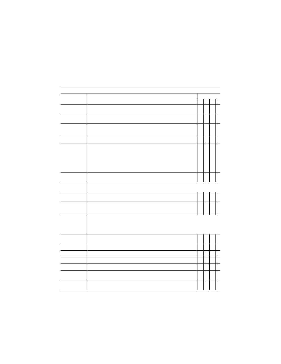
ABLE
A3B—F
UNCTIONS AND
S
UBJECTIVE
T
ESTS
—Continued
QPS Requirements
Entry No.
For qualification at the stated level—Class I airport models
Simulator level
A B C D
2.l. ..................
Representative moving airborne traffic, including the capability to present air hazards
(e.g., airborne traffic on a possible collision course).
X X
2.m. ................
Representative depiction of terrain and obstacles as well as significant and identifiable
natural and cultural features, within 25 NM of the reference airport.
X X
2.n. .................
Appropriate approach lighting systems and airfield lighting for a VFR circuit and land-
ing, non-precision approaches and landings, and Category I, II and III precision ap-
proaches and landings.
X X
2.o. .................
Representative gate docking aids or a marshaller ...........................................................
X
X
2.p. .................
Portrayal of physical relationships known to cause landing illusions (e.g., short run-
ways, landing approaches over water, uphill or downhill runways, rising terrain on
the approach path).
This requirement may be met by a SOC and a demonstration of two landing illusions.
The illusions are not required to be beyond the normal operational capabilities of the
airplane being simulated. The demonstrated illusions must be available to the in-
structor or check airman at the IOS for training, testing, checking, or experience ac-
tivities.
X
2.q. .................
Portrayal of runway surface contaminants, including runway lighting reflections when
wet and partially obscured lights when snow is present, or suitable alternative effects.
X
3. ...........................
Airport model management. The following is the minimum airport model management requirements for
simulators at Levels A, B, C, and D.
3.a. .................
Runway and approach lighting must fade into view in accordance with the environ-
mental conditions set in the simulator, and the distance from the object.
X X X X
3.b. .................
The direction of strobe lights, approach lights, runway edge lights, visual landing aids,
runway centerline lights, threshold lights, and touchdown zone lights must be rep-
licated.
X X X X
4. ...........................
Visual feature recognition. The following is the minimum distances at which runway features must be visi-
ble for simulators at Levels A, B, C, and D. Distances are measured from runway threshold to an airplane
aligned with the runway on an extended 3
°
glide-slope in simulated meteorological conditions that recreate
the minimum distances for visibility. For circling approaches, all tests apply to the runway used for the ini-
tial approach and to the runway of intended landing.
4.a. .................
Runway definition, strobe lights, approach lights, and runway edge white lights from 5
sm (8 km) of the runway threshold.
X X X X
4.b. .................
Visual Approach Aid lights (VASI or PAPI) from 5 sm (8 km) of the runway threshold ..
X
X
4.c. .................
Visual Approach Aid lights (VASI or PAPI) from 3 sm (5 km) of the runway threshold ..
X
X
4.d. .................
Runway centerline lights and taxiway definition from 3 sm (5 km) ..................................
X
X
X
X
4.e. .................
Threshold lights and touchdown zone lights from 2 sm (3 km) ........................................
X
X
X
X
4.f. ..................
Runway markings within range of landing lights for night scenes as required by the
surface resolution test on day scenes.
X X X X
4.g. .................
For circling approaches, the runway of intended landing and associated lighting must
fade into view in a non-distracting manner.
X X X X
VerDate Mar<15>2010
20:48 Jan 30, 2014
Jkt 232047
PO 00000
Frm 00116
Fmt 8010
Sfmt 8002
Q:\14\14V2.TXT
ofr150
PsN: PC150