109
Federal Aviation Administration, DOT
Pt. 60, App. A
T
ABLE
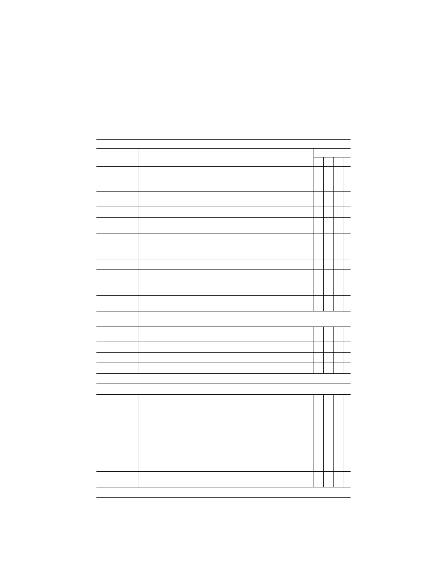
A3B—F
UNCTIONS AND
S
UBJECTIVE
T
ESTS
—Continued
QPS Requirements
Entry No.
For qualification at the stated level—Class I airport models
Simulator level
A B C D
(i) The sound, motion and visual effects of light, medium and heavy precipitation near
a thunderstorm on take-off, approach, and landings at and below an altitude of
2,000 ft (600 m) above the airport surface and within a radius of 10 sm (16 km) from
the airport.
X X
(ii) One airport with a snow scene to include terrain snow and snow-covered taxiways
and runways.
X X
8.b. .................
In-cloud effects such as variable cloud density, speed cues and ambient changes .......
X
X
8.c. .................
The effect of multiple cloud layers representing few, scattered, broken and overcast
conditions giving partial or complete obstruction of the ground scene.
X X
8.d. .................
Visibility and RVR measured in terms of distance. Visibility/RVR checked at 2,000 ft
(600 m) above the airport and at two heights below 2000 ft with at least 500 ft of
separation between the measurements. The measurements must be taken within a
radius of 10 sm (16 km) from the airport.
X X X X
8.e. .................
Patchy fog giving the effect of variable RVR ....................................................................
X X
8.f. ..................
Effects of fog on airport lighting such as halos and defocus ............................................
X X
8.g. .................
Effect of own-ship lighting in reduced visibility, such as reflected glare, including land-
ing lights, strobes, and beacons.
X X
8.h. .................
Wind cues to provide the effect of blowing snow or sand across a dry runway or taxi-
way selectable from the instructor station.
X X
9. ...........................
Instructor control of the following: The following are the minimum instructor controls that must be available
in simulators at Levels A, B, C, and D.
9.a. .................
Environmental effects, e.g., cloud base, cloud effects, cloud density, visibility in statute
miles/kilometers and RVR in feet/meters.
X X X X
9.b. .................
Airport selection .................................................................................................................
X X X X
9.c. .................
Airport lighting, including variable intensity .......................................................................
X
X
X X
9.d. .................
Dynamic effects including ground and flight traffic ...........................................................
X X
End QPS Requirement
Begin Information
10. .........................
An example of being able to ‘‘combine two airport models to achieve two ‘‘in-use’’ run-
ways:
One runway designated as the ‘‘in use’’ runway in the first model of the airport, and
the second runway designated as the ‘‘in use’’ runway in the second model of the
same airport. For example, the clearance is for the ILS approach to Runway 27, Cir-
cle to Land on Runway 18 right. Two airport visual models might be used: the first
with Runway 27 designated as the ‘‘in use’’ runway for the approach to runway 27,
and the second with Runway 18 Right designated as the ‘‘in use’’ runway. When the
pilot breaks off the ILS approach to runway 27, the instructor may change to the
second airport visual model in which runway 18 Right is designated as the ‘‘in use’’
runway, and the pilot would make a visual approach and landing. This process is ac-
ceptable to the FAA as long as the temporary interruption due to the visual model
change is not distracting to the pilot, does not cause changes in navigational radio
frequencies, and does not cause undue instructor/evaluator time.
11. .........................
Sponsors are not required to provide every detail of a runway, but the detail that is
provided should be correct within the capabilities of the system.
End Information
VerDate Mar<15>2010
20:48 Jan 30, 2014
Jkt 232047
PO 00000
Frm 00119
Fmt 8010
Sfmt 8002
Q:\14\14V2.TXT
ofr150
PsN: PC150