332
14 CFR Ch. I (1–1–14 Edition)
Pt. 60, App. D
T
ABLE
D2A—F
LIGHT
T
RAINING
D
EVICE
(FTD) O
BJECTIVE
T
ESTS
—Continued
QPS requirements
Information
Test
Tolerances
Flight conditions
Test details
FTD level
Notes
Entry No.
Title
5 6 7
4. Visual
System
4.a.
........................
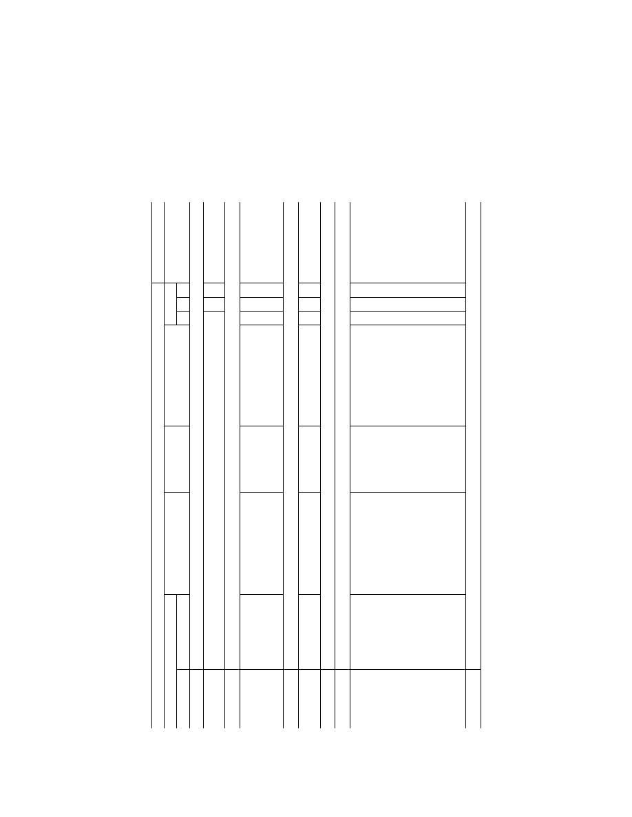
Visual System Response Time: (Choose either test 4.a.1. or 4.a.2. to satisfy test 4.a., Visual Syst
em Response Time Test.
This test is also sufficient for flight deck instrument response timing.)
....
....
4.a.1.
.....................
Latency.
150 ms (or less) after helicopter
response.
Takeoff, climb, and
descent.
One test is required in each axis
(pitch, roll and yaw) for each of
the three conditions (take-off,
cruise, and approach or land-
ing).
X
4.a.2.
.....................
Transport Delay.
150 ms (or less) after controller
movement.
N/A
...........................
A separate test is required in
each axis (pitch, roll, and yaw).
X
4.b.
........................
Field-of-view.
4.b.1.
.....................
Reserved.
4.b.2.
.....................
Continuous visual field-
of-view.
Minimum continuous field-of-view
providing 146
°
horizontal and
36
°
vertical field-of-view for
each pilot simultaneously and
any geometric error between
the Image Generator eye point
and the pilot eye point is 8
°
or
less.
N/A
...........................
An SOC is required and must ex-
plain the geometry of the instal-
lation. Horizontal field-of-view
must not be less than a total of
146
°
(including not less than
73
°
measured either side of the
center of the design eye point).
Additional horizontal field-of-
view capability may be added
at the sponsor’s discretion pro-
vided the minimum field-of-view
is retained. Vertical field-of-
view: Not less than a total of
36
°
measured from the pilot’s
and co-pilot’s eye point.
X
Horizontal field-of-view is
centered on the zero de-
gree azimuth line relative
to the aircraft fuselage.
4.b.3.
.....................
Reserved.
VerDate Mar<15>2010
20:48 Jan 30, 2014
Jkt 232047
PO 00000
Frm 00342
Fmt 8010
Sfmt 8002
Q:\14\14V2.TXT
ofr150
PsN: PC150