585
Federal Aviation Administration, DOT
Pt. 91, SFAR No. 108
T
ABLE
3
TO
A
PPENDIX
A
OF
SFAR 108
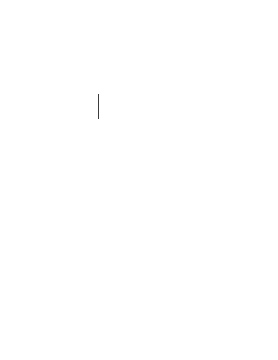
Differences training
2 models currently ..........
1.5 hours at Level A or
B.
More than 2 models cur-
rently.
3 hours at Level A or B.
Each additional model
added.
1.5 hours at Level A or
B.
(e) Definitions of Levels of Training as
Used in This Appendix
(1) LEVEL A Training—Training that is
conducted through self instruction by the
pilot.
(2) LEVEL B Training—Training that is
conducted in the classroom environment
with the aid of a qualified instructor who
meets the requirements of this SFAR.
(3) LEVEL C Training—Training that is ac-
complished in an FAA-approved Level 5, 6, or
7 Flight Training Device (FTD). In addition
to the basic FTD requirements, the FTD
must be representative of the MU–2B cockpit
controls and be specifically approved by the
FAA for the MU–2B airplane.
(4) LEVEL E Training—Training that must
be accomplished in the MU–2B airplane,
Level C simulator, or Level D simulator.
A
PPENDIX
B
TO
SFAR 108—MU–2B G
ROUND
T
RAINING
C
URRICULUM
C
ONTENTS
All items in the ground training cur-
riculum must be covered. The order of pres-
entation is at the discretion of the instruc-
tor. The student must satisfactorily com-
plete a written or oral exam given by the
training provider based on this MU–2B Train-
ing Program.
I. Aircraft General
A. Introduction
B. Airplane (Structures/Aerodynamics/En-
gines) Overview
1. Fuselage
2. Wing
3. Empennage
4. Doors
5. Windshield and Windows
C. Airplane Systems
1. Electrical Power
2. Lighting
3. Fuel System
4. Powerplant
5. Environmental
6. Fire Protection
7. Ice and Rain Protection
8. Landing Gear and Brakes
9. Flight Controls and Trim
10. Pilot Static System/Flight Instruments
11. Oxygen System
D. Operating Limitations
1. Weights
2. Center of Gravity and Loading
3. Airspeeds
4. Maneuvering Load Factors
5. Takeoff And Landing Operations
6. Enroute Operations
E. Required Placards
F. Instrument Markings
G. Flight Characteristics
1. Control System
2. Stability and Stall Characteristics
3. Single Engine Operation
4. Maneuvering and Trim
5. Takeoff and Landing
II. Electrical Power
A. General Description
B. DC Electrical System
1. DC Power Generation
2. DC Power Distribution
3. Battery System
4. External Power System
C. AC Electrical System
1. AC Power Generation
2. Controls and Indicators
3. AC Power Distribution
D. Limitations
1. General Limitations
2. Instrument Markings
III. Lighting
A. Exterior Lighting System
1. Navigation Lights
2. Anti-Collision Lights
3. Wing Inspection Lights
4. Taxi Lights
5. Landing Lights
6. Rotating Beacon
7. Operation
B. Interior Lighting System
1. Flight Compartment Lights
2. Passenger Compartment Lights
C. Emergency Lighting System
1. Cockpit Emergency Lighting
2. Aircraft Emergency Lighting
D. Procedures
1. Normal
2. Abnormal
3. Emergency
IV. Master Caution System
A. System Description and Operation
1. Master Caution Light and Reset Switch
2. Annunciator and Indicator Panels
3. Operation Lights
4. System Tests
B. Procedures
V. Fuel System
A. Fuel Storage
1. Refueling/Balancing
2. De-Fueling and Draining
3. Tank Vent System
B. Fuel Distribution
1. Fuel Transfer
2. Fuel Balancing
3. Boost Pump Operation
C. Fuel Indicating
1. Fuel Quantity
2. Low Fuel Warning
D. Fuel System Limitations
1. Approved Fuels
2. Fuel Anti-Icing Additives
3. Fuel Temperature Limitations
4. Fuel Transfer and Fuel Imbalance
VerDate Mar<15>2010
20:48 Jan 30, 2014
Jkt 232047
PO 00000
Frm 00595
Fmt 8010
Sfmt 8002
Q:\14\14V2.TXT
ofr150
PsN: PC150