6. U.S. Government charts depict TAAs using will show all TAA minimum altitudes and sector/ra-
icons located in the plan view outside the depiction of dius subdivisions. The IAF for each area of the TAA
the actual approach procedure. (See FIG 5-4-5). Use is included on the icon where it appears on the ap-
of icons is necessary to avoid obscuring any portion proach to help the pilot orient the icon to the approach
of the "T" procedure (altitudes, courses, minimum procedure. The IAF name and the distance of the TAA
altitudes, etc.). The icon for each TAA area will be area boundary from the IAF are included on the out-
located and oriented on the plan view with respect to side arc of the TAA area icon.
the direction of arrival to the approach procedure, and
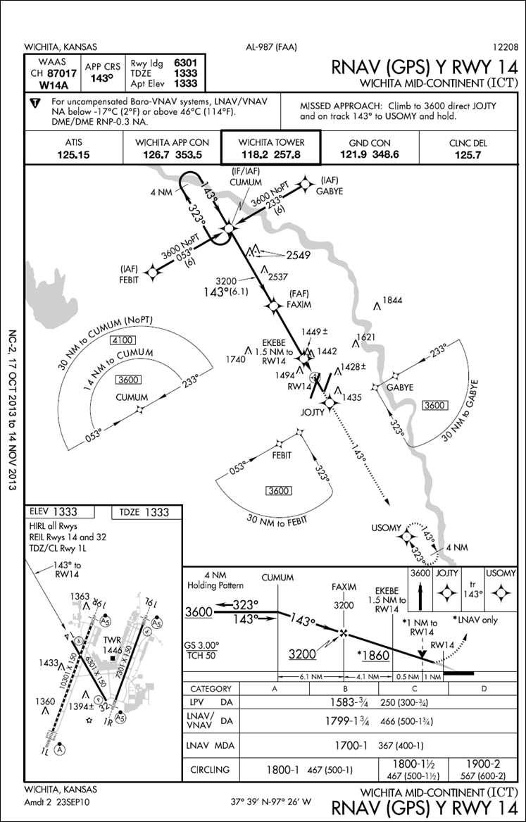
FIG 5-4-5
RNAV (GPS)
Approach Chart
5-4-12 Arrival Procedures