335
Federal Aviation Administration, DOT
Pt. 23, App. A
gusts, the most severe loads must be consid-
ered in association with every center of pres-
sure position between the leading edge and
the half chord of the mean chord of the sur-
face (stabilizer and elevator, or fin and rud-
der).
(iv) To ensure adequate strength under
high leading edge loads, the most severe sta-
bilizer and fin loads must be further consid-
ered as being increased by 50 percent over
the leading 10 percent of the chord with the
loads aft of this appropriately decreased to
retain the same total load.
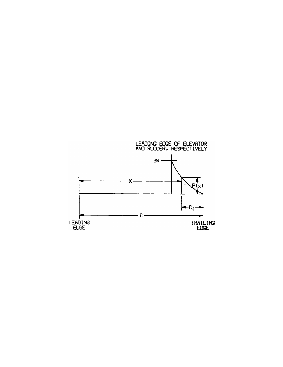
(v) The most severe elevator and rudder
loads should be further considered as being
distributed parabolically from three times
the mean loading of the surface (stabilizer
and elevator, or fin and rudder) at the lead-
ing edge of the elevator and rudder, respec-
tively, to zero at the trailing edge according
to the equation:
P x
w
c
x
c
f
( )
( )
(
)
=
−
3
2
2
Where—
P(x)=local pressure at the chordwise stations
x,
c=chord length of the tail surface,
c
f
=chord length of the elevator and rudder
respectively, and
w
¯ =average surface loading as specified in
Figure A5.
(vi) The chordwise loading distribution for
ailerons, wing flaps, and trim tabs are speci-
fied in Table 2 of this appendix.
(2) If certification in the acrobatic cat-
egory is desired, the horizontal tail must be
investigated for an unsymmetrical load of
100 percent
w on one side of the airplane cen-
terline and 50 percent on the other side of
the airplane centerline.
(d)
Outboard fins. Outboard fins must meet
the requirements of § 23.445.
(e)
Special devices. Special devices must
meet the requirements of § 23.459.
A23.13
Control system loads.
(a)
Primary flight controls and systems. Each
primary flight control and system must be
designed as follows:
(1) The flight control system and its sup-
porting structure must be designed for loads
corresponding to 125 percent of the computed
hinge moments of the movable control sur-
face in the conditions prescribed in A23.11 of
this appendix. In addition—
(i) The system limit loads need not exceed
those that could be produced by the pilot and
automatic devices operating the controls;
and
(ii) The design must provide a rugged sys-
tem for service use, including jamming,
ground gusts, taxiing downwind, control in-
ertia, and friction.
(2) Acceptable maximum and minimum
limit pilot forces for elevator, aileron, and
rudder controls are shown in the table in
§ 23.397(b). These pilots loads must be as-
sumed to act at the appropriate control grips
VerDate Mar<15>2010
10:12 Mar 18, 2014
Jkt 232046
PO 00000
Frm 00345
Fmt 8010
Sfmt 8002
Y:\SGML\232046.XXX
232046
ER09FE96.004</MATH>
ER09FE96.007</GPH>
pmangrum on DSK3VPTVN1PROD with CFR