342
14 CFR Ch. I (1–1–14 Edition)
Pt. 23, App. C
F
IGURE
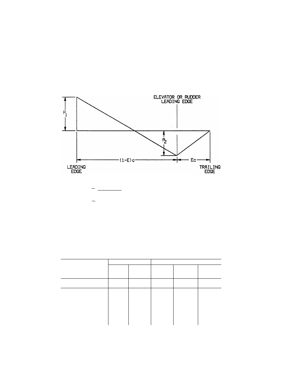
A7—C
HORDWISE
L
OAD
D
ISTRIBUTION FOR
S
TABILIZER AND
E
LEVATOR OR
F
IN AND
R
UDDER
P
w
E
d
E
P
w
d
E
1
2
2
2
3
1
2
3
1
=
− −
−
=
+ −
( )
(
' )
(
)
( ) (
'
)
where:
w
¯ =average surface loading (as specified in
figure A.5)
E=ratio of elevator (or rudder) chord to total
stabilizer and elevator (or fin and rudder)
chord.
d
′
=ratio of distance of center of pressure of a
unit spanwise length of combined sta-
bilizer and elevator (or fin and rudder)
measured from stabilizer (or fin) leading
edge to the local chord. Sign convention
is positive when center of pressure is be-
hind leading edge.
c=local chord.
N
OTE
: Positive values of w
¯ , P
1
and P
2
are
all measured in the same direction.
[Doc. No. 4080, 29 FR 17955, Dec. 18, 1964, as
amended by Amdt. 23–7, 34 FR 13097, Aug. 13,
1969; 34 FR 14727, Sept. 24, 1969; Amdt. 23–16,
40 FR 2577, Jan. 14, 1975; Amdt. 23–28, 47 FR
13315, Mar. 29, 1982; Amdt. 23–48, 61 FR 5149,
Feb. 9, 1996]
A
PPENDIX
B
TO
P
ART
23 [R
ESERVED
]
A
PPENDIX
C
TO
P
ART
23—B
ASIC
L
ANDING
C
ONDITIONS
[C23.1 Basic landing conditions]
Condition
Tail wheel type
Nose wheel type
Level landing
Tail-down land-
ing
Level landing
with inclined
reactions
Level landing
with nose wheel
just clear of
ground
Tail-down land-
ing
Reference section .............................
23.479(a)(1)
23.481(a)(1) ....
23.479(a)(2)(i)
23.479(a)(2)(ii) ...
23.481(a)(2) and
(b).
Vertical component at c. g ................
nW ................
nW ..................
nW ..................
nW .....................
nW.
Fore and aft component at c. g ........
KnW .............
0 ......................
KnW ................
KnW ...................
0.
Lateral component in either direction
at c. g.
0 ...................
0 ......................
0 ......................
0 .........................
0.
Shock absorber extension (hydraulic
shock absorber).
Note (2) ........
Note (2) ..........
Note (2) ..........
Note (2) .............
Note (2).
Shock absorber deflection (rubber or
spring shock absorber), percent.
100 ...............
100 ..................
100 ..................
100 .....................
100.
Tire deflection ...................................
Static ............
Static ...............
Static ...............
Static ..................
Static.
Main wheel loads (both wheels) (Vr) (n-L)W ..........
(n-L)W b/d ......
(n-L)W a
′
/d
′
.....
(n-L)W ................
(n-L)W.
Main wheel loads (both wheels) (Dr)
KnW .............
0 ......................
KnW a
′
/d
′
........
KnW ...................
0.
VerDate Mar<15>2010
10:12 Mar 18, 2014
Jkt 232046
PO 00000
Frm 00352
Fmt 8010
Sfmt 8002
Y:\SGML\232046.XXX
232046
ER09FE96.009</GPH>
ER09FE96.005</GPH>
pmangrum on DSK3VPTVN1PROD with CFR