343
Federal Aviation Administration, DOT
Pt. 23, App. D
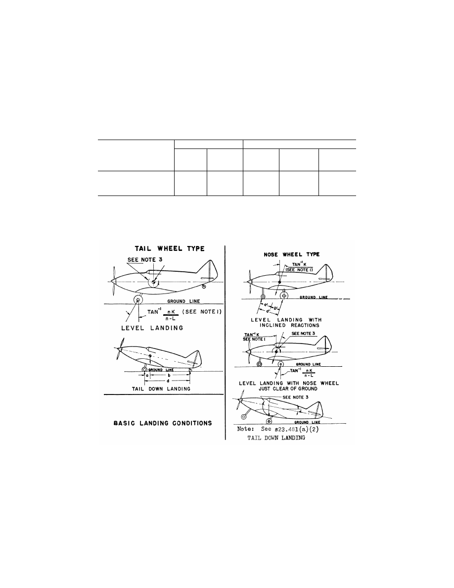
[C23.1 Basic landing conditions]
Condition
Tail wheel type
Nose wheel type
Level landing
Tail-down land-
ing
Level landing
with inclined
reactions
Level landing
with nose wheel
just clear of
ground
Tail-down land-
ing
Tail (nose) wheel loads (Vf) .............
0 ...................
(n-L)W a/d ......
(n-L)W b
′
/d
′
.....
0 .........................
0.
Tail (nose) wheel loads (Df) .............
0 ...................
0 ......................
KnW b
′
/d
′
........
0 .........................
0.
Notes .................................................
(1), (3), and
(4).
(4) ...................
(1) ...................
(1), (3), and (4) ..
(3) and (4).
N
OTE
(1). K may be determined as follows: K=0.25 for W=3,000 pounds or less; K=0.33 for W=6,000 pounds or greater, with
linear variation of K between these weights.
N
OTE
(2). For the purpose of design, the maximum load factor is assumed to occur throughout the shock absorber stroke from
25 percent deflection to 100 percent deflection unless otherwise shown and the load factor must be used with whatever shock
absorber extension is most critical for each element of the landing gear.
N
OTE
(3). Unbalanced moments must be balanced by a rational or conservative method.
N
OTE
(4). L is defined in § 23.725(b).
N
OTE
(5). n is the limit inertia load factor, at the c.g. of the airplane, selected under § 23.473 (d), (f), and (g).
[Doc. No. 4080, 29 FR 17955, Dec. 18, 1964, as amended by Amdt. 23–7, 34 FR 13099, Aug. 13, 1969]
A
PPENDIX
D
TO
P
ART
23—W
HEEL
S
PIN
-
U
P AND
S
PRING
-B
ACK
L
OADS
D23.1
Wheel spin-up loads.
(a) The following method for determining
wheel spin-up loads for landing conditions is
based on NACA T.N. 863. However, the drag
component used for design may not be less
than the drag load prescribed in § 23.479(b).
F
Hmax
=1/
r
e
√
2I
w
(
V
H
—
V
c
)
nF
Vmax
/
t
S
where—
F
Hmax
=maximum rearward horizontal force
acting on the wheel (in pounds);
r
e
=effective rolling radius of wheel under im-
pact based on recommended operating
tire pressure (which may be assumed to
be equal to the rolling radius under a
static load of
n
j
W
e
) in feet;
VerDate Mar<15>2010
10:12 Mar 18, 2014
Jkt 232046
PO 00000
Frm 00353
Fmt 8010
Sfmt 8002
Y:\SGML\232046.XXX
232046
EC28SE91.029</GPH>
pmangrum on DSK3VPTVN1PROD with CFR