352
14 CFR Ch. I (1–1–14 Edition)
Pt. 23, App. F
(9)
Instrumentation. Provide a calibrated re-
cording device with an appropriate range or
a computerized data acquisition system to
measure and record the outputs of the calo-
rimeter and the thermocouple. The data ac-
quisition system must be capable of record-
ing the calorimeter output every second dur-
ing calibration.
(10)
Timing device. Provide a stopwatch or
other device, accurate to
±
1 second/hour, to
measure the time of application of the pilot
burner flame.
(c)
Test specimens.
(1)
Specimen preparation. Prepare and test a
minimum of three test specimens. If an ori-
ented film cover material is used, prepare
and test both the warp and fill directions.
(2)
Construction. Test specimens must in-
clude all materials used in construction of
the insulation (including batting, film,
scrim, tape,
etc.). Cut a piece of core mate-
rial such as foam or fiberglass, and cut a
piece of film cover material (if used) large
enough to cover the core material. Heat seal-
ing is the preferred method of preparing fi-
berglass samples, since they can be made
without compressing the fiberglass (‘‘box
sample’’). Cover materials that are not heat
sealable may be stapled, sewn, or taped as
long as the cover material is sufficiently
over-cut to be drawn down the sides without
compressing the core material. The fas-
tening means should be as continuous as pos-
sible along the length of the seams. The
specimen thickness must be of the same
thickness as installed in the airplane.
(3)
Specimen Dimensions. To facilitate prop-
er placement of specimens in the sliding
platform housing, cut non-rigid core mate-
rials, such as fiberglass, 12
1
⁄
2
inches (318mm)
wide by 23 inches (584mm) long. Cut rigid
materials, such as foam, 11
1
⁄
2
±
1
⁄
4
inches (292
mm
±
6mm) wide by 23 inches (584mm) long in
order to fit properly in the sliding platform
housing and provide a flat, exposed surface
equal to the opening in the housing.
(d)
Specimen conditioning. Condition the
test specimens at 70
±
5
°
F (21
±
2
°
C) and 55
percent
±
10 percent relative humidity, for a
minimum of 24 hours prior to testing.
(e)
Apparatus Calibration.
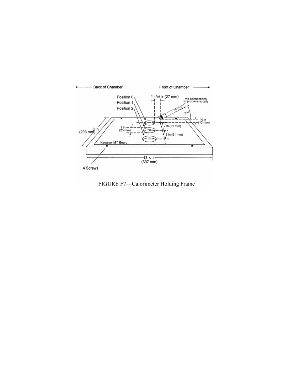
(1) With the sliding platform out of the
chamber, install the calorimeter holding
frame. Push the platform back into the
chamber and insert the calorimeter into the
first hole (‘‘zero’’ position). See figure F7.
Close the bottom door located below the slid-
ing platform. The distance from the center-
line of the calorimeter to the radiant panel
surface at this point must be 7
1
⁄
2
inches
±
1
⁄
8
(191 mm
±
3). Before igniting the radiant
panel, ensure that the calorimeter face is
clean and that there is water running
through the calorimeter.
(2) Ignite the panel. Adjust the fuel/air
mixture to achieve 1.5 BTUs/feet
2
-second
±
5
percent (1.7 Watts/cm
2
±
5 percent) at the
‘‘zero’’ position. If using an electric panel,
set the power controller to achieve the prop-
er heat flux. Allow the unit to reach steady
state (this may take up to 1 hour). The pilot
burner must be off and in the down position
during this time.
VerDate Mar<15>2010
10:12 Mar 18, 2014
Jkt 232046
PO 00000
Frm 00362
Fmt 8010
Sfmt 8002
Y:\SGML\232046.XXX
232046
ER02DE11.093</GPH>
pmangrum on DSK3VPTVN1PROD with CFR