353
Federal Aviation Administration, DOT
Pt. 23, App. F
(3) After steady-state conditions have been
reached, move the calorimeter 2 inches (51
mm) from the ‘‘zero’’ position (first hole) to
position 1 and record the heat flux. Move the
calorimeter to position 2 and record the heat
flux. Allow enough time at each position for
the calorimeter to stabilize. Table 1 depicts
typical calibration values at the three posi-
tions.
T
ABLE
1—C
ALIBRATION
T
ABLE
Position BTU/feet
2
sec Watts/cm
2
‘‘Zero’’ Position ..
1.5
1.7
Position 1 ...........
1.51–1.50–1.49
1.71–1.70–1.69
Position 2 ...........
1.43–1.44
1.62–1.63
(4) Open the bottom door, remove the calo-
rimeter and holder fixture. Use caution as
the fixture is very hot.
(f)
Test Procedure.
(1) Ignite the pilot burner. Ensure that it is
at least 2 inches (51 mm) above the top of the
platform. The burner may not contact the
specimen until the test begins.
(2) Place the test specimen in the sliding
platform holder. Ensure that the test sample
surface is level with the top of the platform.
At ‘‘zero’’ point, the specimen surface must
be 7
1
⁄
2
inches
±
1
⁄
8
inch (191 mm
±
3) below the
radiant panel.
(3) Place the retaining/securing frame over
the test specimen. It may be necessary (due
to compression) to adjust the sample (up or
down) in order to maintain the distance from
the sample to the radiant panel (7
1
⁄
2
inches
±
1
⁄
8
inch (191 mm
±
3) at ‘‘zero’’ position). With
film/fiberglass assemblies, it is critical to
make a slit in the film cover to purge any air
inside. This allows the operator to maintain
the proper test specimen position (level with
the top of the platform) and to allow ventila-
tion of gases during testing. A longitudinal
slit, approximately 2 inches (51mm) in
length, must be centered 3 inches
±
1
⁄
2
inch
(76mm
±
13mm) from the left flange of the se-
curing frame. A utility knife is acceptable
for slitting the film cover.
(4) Immediately push the sliding platform
into the chamber and close the bottom door.
(5) Bring the pilot burner flame into con-
tact with the center of the specimen at the
‘‘zero’’ point and simultaneously start the
timer. The pilot burner must be at a 27 de-
gree angle with the sample and be approxi-
mately
1
⁄
2
inch (12 mm) above the sample.
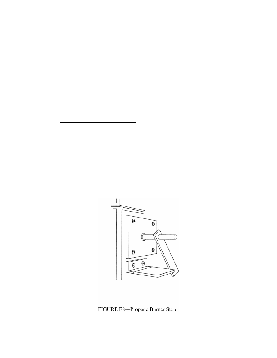
See figure F7. A stop, as shown in figure F8,
allows the operator to position the burner
correctly each time.
VerDate Mar<15>2010
10:12 Mar 18, 2014
Jkt 232046
PO 00000
Frm 00363
Fmt 8010
Sfmt 8006
Y:\SGML\232046.XXX
232046
ER02DE11.094</GPH>
pmangrum on DSK3VPTVN1PROD with CFR