410
14 CFR Ch. I (1–1–14 Edition)
§ 25.427
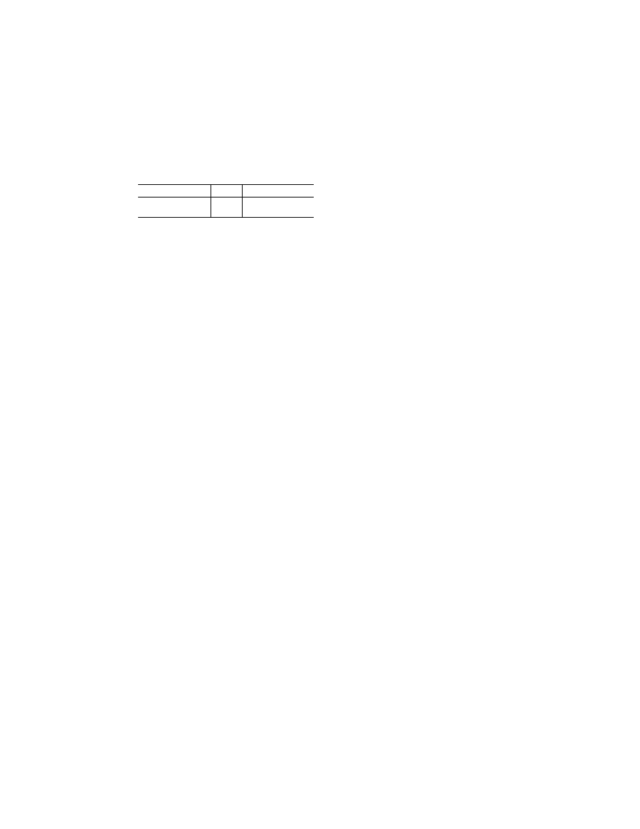
Surface
K
Position of controls
(e) Rudder ....................
0.75 (e) Rudder in neutral.
(f) ......do .......................
0.75 (f) Rudder at full throw.
1
A positive value of K indicates a moment tending to de-
press the surface, while a negative value of K indicates a mo-
ment tending to raise the surface.
[Doc. No. 5066, 29 FR 18291, Dec. 24, 1964, as
amended by Amdt. 25–72, 55 FR 29776, July 20,
1990; Amdt. 25–91, 62 FR 40705, July 29, 1997]
§ 25.427
Unsymmetrical loads.
(a) In designing the airplane for lat-
eral gust, yaw maneuver and roll ma-
neuver conditions, account must be
taken of unsymmetrical loads on the
empennage arising from effects such as
slipstream and aerodynamic inter-
ference with the wing, vertical fin and
other aerodynamic surfaces.
(b) The horizontal tail must be as-
sumed to be subjected to unsymmet-
rical loading conditions determined as
follows:
(1) 100 percent of the maximum load-
ing from the symmetrical maneuver
conditions of § 25.331 and the vertical
gust conditions of § 25.341(a) acting sep-
arately on the surface on one side of
the plane of symmetry; and
(2) 80 percent of these loadings acting
on the other side.
(c) For empennage arrangements
where the horizontal tail surfaces have
dihedral angles greater than plus or
minus 10 degrees, or are supported by
the vertical tail surfaces, the surfaces
and the supporting structure must be
designed for gust velocities specified in
§ 25.341(a) acting in any orientation at
right angles to the flight path.
(d) Unsymmetrical loading on the
empennage arising from buffet condi-
tions of § 25.305(e) must be taken into
account.
[Doc. No. 27902, 61 FR 5222, Feb. 9, 1996]
§ 25.445
Auxiliary aerodynamic sur-
faces.
(a) When significant, the aero-
dynamic influence between auxiliary
aerodynamic surfaces, such as out-
board fins and winglets, and their sup-
porting aerodynamic surfaces, must be
taken into account for all loading con-
ditions including pitch, roll, and yaw
maneuvers, and gusts as specified in
§ 25.341(a) acting at any orientation at
right angles to the flight path.
(b) To provide for unsymmetrical
loading when outboard fins extend
above and below the horizontal surface,
the critical vertical surface loading
(load per unit area) determined under
§ 25.391 must also be applied as follows:
(1) 100 percent to the area of the
vertical surfaces above (or below) the
horizontal surface.
(2) 80 percent to the area below (or
above) the horizontal surface.
[Doc. No. 5066, 29 FR 18291, Dec. 24, 1964, as
amended by Amdt. 25–86, 61 FR 5222, Feb. 9,
1996]
§ 25.457
Wing flaps.
Wing flaps, their operating mecha-
nisms, and their supporting structures
must be designed for critical loads oc-
curring in the conditions prescribed in
§ 25.345, accounting for the loads occur-
ring during transition from one flap po-
sition and airspeed to another.
§ 25.459
Special devices.
The loading for special devices using
aerodynamic surfaces (such as slots,
slats and spoilers) must be determined
from test data.
[Doc. No. 5066, 29 FR 18291, Dec. 24, 1964, as
amended by Amdt. 25–72, 55 FR 29776, July 20,
1990]
G
ROUND
L
OADS
§ 25.471
General.
(a)
Loads and equilibrium. For limit
ground loads—
(1) Limit ground loads obtained
under this subpart are considered to be
external forces applied to the airplane
structure; and
(2) In each specified ground load con-
dition, the external loads must be
placed in equilibrium with the linear
and angular inertia loads in a rational
or conservative manner.
(b)
Critical centers of gravity. The crit-
ical centers of gravity within the range
for which certification is requested
must be selected so that the maximum
design loads are obtained in each land-
ing gear element. Fore and aft,
vertical, and lateral airplane centers of
gravity must be considered. Lateral
displacements of the c.g. from the air-
plane centerline which would result in
main gear loads not greater than 103
percent of the critical design load for
VerDate Mar<15>2010
10:12 Mar 18, 2014
Jkt 232046
PO 00000
Frm 00420
Fmt 8010
Sfmt 8010
Y:\SGML\232046.XXX
232046
pmangrum on DSK3VPTVN1PROD with CFR