427
Federal Aviation Administration, DOT
§ 25.629
flight control systems, control surface
hinges and balance weight attach-
ments, seat, berth, safety belt, and fuel
and oil tank supports and attachments,
and cabin pressure valves.
(d)
Noncritical castings. For each cast-
ing other than those specified in para-
graph (c) of this section, the following
apply:
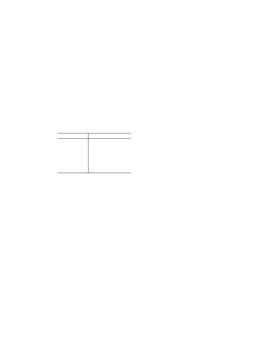
(1) Except as provided in paragraphs
(d)(2) and (3) of this section, the casting
factors and corresponding inspections
must meet the following table:
Casting factor
Inspection
2.0 or more ...................
100 percent visual.
Less than 2.0 but more
than 1.5.
100 percent visual, and magnetic
particle or penetrant or equiva-
lent nondestructive inspection
methods.
1.25 through 1.50 ..........
100 percent visual, magnetic par-
ticle or penetrant, and radio-
graphic, or approved equivalent
nondestructive inspection meth-
ods.
(2) The percentage of castings in-
spected by nonvisual methods may be
reduced below that specified in para-
graph (d)(1) of this section when an ap-
proved quality control procedure is es-
tablished.
(3) For castings procured to a speci-
fication that guarantees the mechan-
ical properties of the material in the
casting and provides for demonstration
of these properties by test of coupons
cut from the castings on a sampling
basis—
(i) A casting factor of 1.0 may be
used; and
(ii) The castings must be inspected as
provided in paragraph (d)(1) of this sec-
tion for casting factors of ‘‘1.25 through
1.50’’ and tested under paragraph (c)(2)
of this section.
§ 25.623
Bearing factors.
(a) Except as provided in paragraph
(b) of this section, each part that has
clearance (free fit), and that is subject
to pounding or vibration, must have a
bearing factor large enough to provide
for the effects of normal relative mo-
tion.
(b) No bearing factor need be used for
a part for which any larger special fac-
tor is prescribed.
§ 25.625
Fitting factors.
For each fitting (a part or terminal
used to join one structural member to
another), the following apply:
(a) For each fitting whose strength is
not proven by limit and ultimate load
tests in which actual stress conditions
are simulated in the fitting and sur-
rounding structures, a fitting factor of
at least 1.15 must be applied to each
part of—
(1) The fitting;
(2) The means of attachment; and
(3) The bearing on the joined mem-
bers.
(b) No fitting factor need be used—
(1) For joints made under approved
practices and based on comprehensive
test data (such as continuous joints in
metal plating, welded joints, and scarf
joints in wood); or
(2) With respect to any bearing sur-
face for which a larger special factor is
used.
(c) For each integral fitting, the part
must be treated as a fitting up to the
point at which the section properties
become typical of the member.
(d) For each seat, berth, safety belt,
and harness, the fitting factor specified
in § 25.785(f)(3) applies.
[Doc. No. 5066, 29 FR 18291, Dec. 24, 1964, as
amended by Amdt. 25–23, 35 FR 5674, Apr. 8,
1970; Amdt. 25–72, 55 FR 29776, July 20, 1990]
§ 25.629
Aeroelastic stability require-
ments.
(a)
General. The aeroelastic stability
evaluations required under this section
include flutter, divergence, control re-
versal and any undue loss of stability
and control as a result of structural de-
formation. The aeroelastic evaluation
must include whirl modes associated
with any propeller or rotating device
that contributes significant dynamic
forces. Compliance with this section
must be shown by analyses, wind tun-
nel tests, ground vibration tests, flight
tests, or other means found necessary
by the Administrator.
(b)
Aeroelastic stability envelopes. The
airplane must be designed to be free
from aeroelastic instability for all con-
figurations and design conditions with-
in the aeroelastic stability envelopes
as follows:
VerDate Mar<15>2010
10:12 Mar 18, 2014
Jkt 232046
PO 00000
Frm 00437
Fmt 8010
Sfmt 8010
Y:\SGML\232046.XXX
232046
pmangrum on DSK3VPTVN1PROD with CFR