AIM
4/3/14
5−4−51
Arrival Procedures
5
−
4
−
19. Side
−
step Maneuver
a.
ATC may authorize a standard instrument
approach procedure which serves either one of
parallel runways that are separated by 1,200 feet or
less followed by a straight−in landing on the adjacent
runway.
b.
Aircraft that will execute a side−step maneuver
will be cleared for a specified approach procedure
and landing on the adjacent parallel runway.
Example, “cleared ILS runway 7 left approach,
side−step to runway 7 right.” Pilots are expected to
commence the side−step maneuver as soon as
possible after the runway or runway environment is
in sight. Compliance with minimum altitudes
associated with stepdown fixes is expected even after
the side−step maneuver is initiated.
NOTE
−
Side
−step minima are flown to a Minimum Descent
Altitude (MDA) regardless of the approach authorized.
c.
Landing minimums to the adjacent runway will
be based on nonprecision criteria and therefore higher
than the precision minimums to the primary runway,
but will normally be lower than the published circling
minimums.
5
−
4
−
20. Approach and Landing Minimums
a. Landing Minimums.
The rules applicable to
landing minimums are contained in 14 CFR
Section 91.175. TBL 5−4−1 may be used to convert
RVR to ground or flight visibility. For converting
RVR values that fall between listed values, use the
next higher RVR value; do not interpolate. For
example, when converting 1800 RVR, use 2400 RVR
with the resultant visibility of
1
/
2
mile.
b. Obstacle Clearance.
Final approach obstacle
clearance is provided from the start of the final
segment to the runway or missed approach point,
whichever occurs last. Side−step obstacle protection
is provided by increasing the width of the final
approach obstacle clearance area.
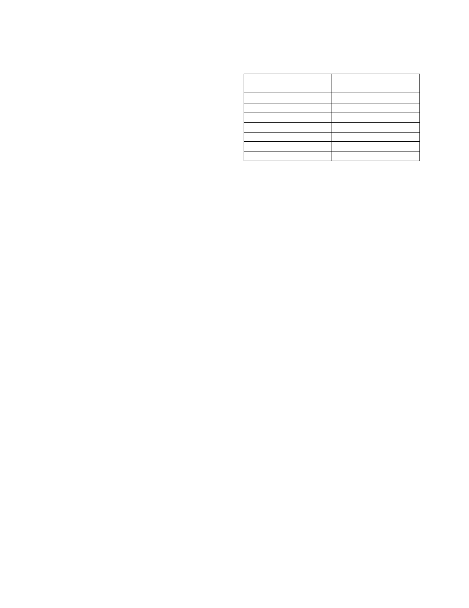
TBL 5
−4−1
RVR Value Conversions
RVR
Visibility
(statute miles)
1600
1
/
4
2400
1
/
2
3200
5
/
8
4000
3
/
4
4500
7
/
8
5000
1
6000
1
1
/
4
1.
Circling approach protected areas are defined
by the tangential connection of arcs drawn from each
runway end (see FIG 5−4−27). Circling approach
protected areas developed prior to late 2012 used
fixed radius distances, dependent on aircraft
approach category, as shown in the table on page B2
of the U.S. TPP. The approaches using standard
circling approach areas can be identified by the
absence of the “negative C” symbol on the circling
line of minima. Circling approach protected areas
developed after late 2012 use the radius distance
shown in the table on page B2 of the U.S. TPP,
dependent on aircraft approach category, and the
altitude of the circling MDA, which accounts for true
airspeed increase with altitude. The approaches using
expanded circling approach areas can be identified by
the presence of the “negative C” symbol on the
circling line of minima (see FIG 5−4−28). Because of
obstacles near the airport, a portion of the circling
area may be restricted by a procedural note; for
example, “Circling NA E of RWY 17−35.” Obstacle
clearance is provided at the published minimums
(MDA) for the pilot who makes a straight−in
approach, side−steps, or circles. Once below the
MDA the pilot must see and avoid obstacles.
Executing the missed approach after starting to
maneuver usually places the aircraft beyond the
MAP. The aircraft is clear of obstacles when at or
above the MDA while inside the circling area, but
simply joining the missed approach ground track
from the circling maneuver may not provide vertical
obstacle clearance once the aircraft exits the circling
area. Additional climb inside the circling area may be
required before joining the missed approach track.
See Paragraph 5−4−21, Missed Approach, for
additional considerations when starting a missed
approach at other than the MAP.