AIM
4/3/14
1−1−10
Navigation Aids
length. Airborne marker beacon receivers with a
selective sensitivity feature should always be
operated in the “low” sensitivity position for proper
reception of ILS marker beacons.
2.
Ordinarily, there are two marker beacons
associated with an ILS, the OM and MM. Locations
with a Category II ILS also have an Inner
Marker (IM). When an aircraft passes over a marker,
the pilot will receive the indications shown in
(a)
The OM normally indicates a position at
which an aircraft at the appropriate altitude on the
localizer course will intercept the ILS glide path.
(b)
The MM indicates a position approxim-
ately 3,500 feet from the landing threshold. This is
also the position where an aircraft on the glide path
will be at an altitude of approximately 200 feet above
the elevation of the touchdown zone.
(c)
The IM will indicate a point at which an
aircraft is at a designated decision height (DH) on the
glide path between the MM and landing threshold.
TBL 1
−1−3
Marker Passage Indications
Marker
Code
Light
OM
* * *
BLUE
MM
D * D *
AMBER
IM
D D D D
WHITE
BC
D D D D
WHITE
3.
A back course marker normally indicates the
ILS back course final approach fix where approach
descent is commenced.
g. Compass Locator
1.
Compass locator transmitters are often
situated at the MM and OM sites. The transmitters
have a power of less than 25 watts, a range of at least
15 miles and operate between 190 and 535 kHz. At
some locations, higher powered radio beacons, up to
400 watts, are used as OM compass locators. These
generally carry Transcribed Weather Broadcast
(TWEB) information.
2.
Compass locators transmit two letter identi-
fication groups. The outer locator transmits the first
two letters of the localizer identification group, and
the middle locator transmits the last two letters of the
localizer identification group.
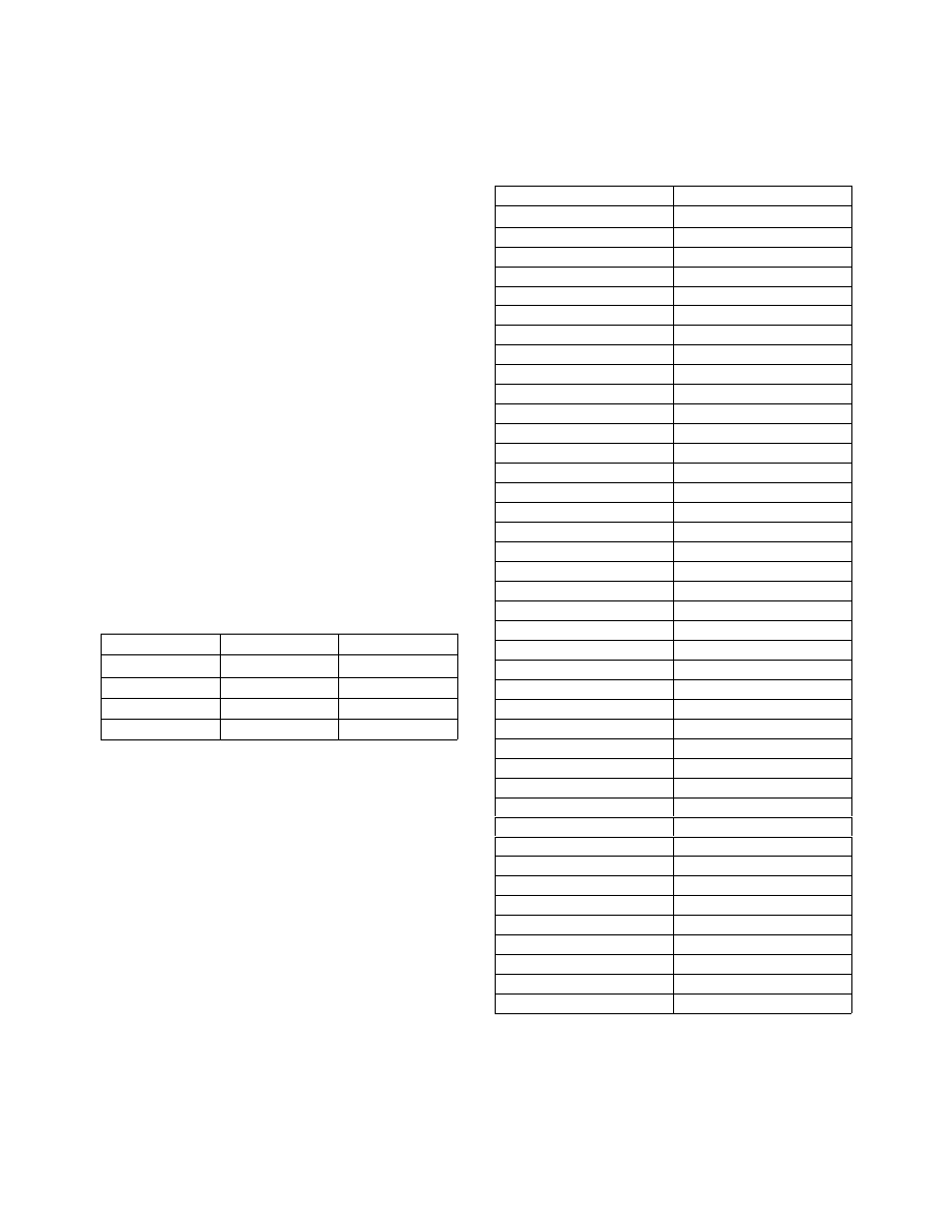
h. ILS Frequency
TBL 1
−1−4
Frequency Pairs Allocated for ILS
Localizer MHz
Glide Slope
108.10
334.70
108.15
334.55
108.3
334.10
108.35
333.95
108.5
329.90
108.55
329.75
108.7
330.50
108.75
330.35
108.9
329.30
108.95
329.15
109.1
331.40
109.15
331.25
109.3
332.00
109.35
331.85
109.50
332.60
109.55
332.45
109.70
333.20
109.75
333.05
109.90
333.80
109.95
333.65
110.1
334.40
110.15
334.25
110.3
335.00
110.35
334.85
110.5
329.60
110.55
329.45
Localizer MHz
Glide Slope
110.70
330.20
110.75
330.05
110.90
330.80
110.95
330.65
111.10
331.70
111.15
331.55
111.30
332.30
111.35
332.15
111.50
332.9
111.55
332.75
111.70
333.5
111.75
333.35
111.90
331.1
111.95
330.95
i. ILS Minimums
1.
The lowest authorized ILS minimums, with
all required ground and airborne systems components
operative, are: